shape
carat
color
clarity

A new article published by a long time diamond cut investigator.

oldminer

Ideal_Rock
Trade
Joined
Sep 3, 2000
Messages
6,730
Something to be learned for those who are curious. Thought it may appeal to some of the participants on the forum.
xxxxxxxxxxxxxxxxxxxxxxxxxxxxxxxxxxxxxxxxxxxxxxxxxxxxxxxxxxxxxxxxxxxxxxxxxxxxxxxxxxxxxxxxxxxxxxxxxxxxxxxxx

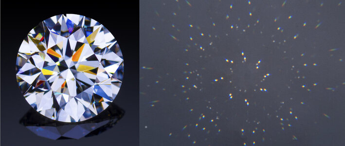
Discover the ‘Diamond’s Spectral Constellation’. Michael Cowing explains why the ‘Spectral Constellation’ is the ‘nexus’ connecting a diamond cut’s light performance and its illumination and why it is the key to understanding the occurrence of fire in a diamond when used as a gemstone optical analysis technique.

https://acagemlab.com/ideal-brilliant-cut-and-spectral-constellation/

Michael D Cowing, M.Sc, FGA
AGA Certified Gem Laboratory
 
Hi Dave,
Thanks for posting. I read through it and hope that it will help some of our readers understand some of the factors that they enjoy when looking at their diamonds.

A couple of points to assist. As John Pollard pointed out in one of his education updates. The transition from dark to blue to bright white to orange to black, or the other way around - black orange white blue black - as we rock a diamond and watch a facet change and flash for our pleasure explains the usual absence of green fire.

Green is joined by orange and indigo paler blue - those three merge into white.

An interesting diversion - it appear Michael's photos in fig 16 and 17 of the dull facets are indicating internal graining in the diamond.
1628724063591.png
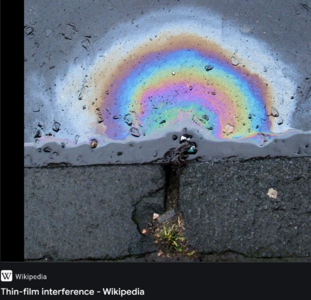
The colors in both the right side facets are like the oily water colors you see on a garage floor. They are caused by thin film distortion of light waves.
Here is an example in a stone I saw recently of an intensely grainy diamond.
1628724198213.png
I had sent the above image to one of my retired scientist friends, Grant Pearson, who has time to write long replies:
Morning Garry, I see what you mean, very obvious 'isochromes' development, ie the differential interference colour effects due to internal strain causing ABR, (ie anomalous birefringence), seen normally only between crossed polars. It's sometimes even seen with just a single polar, like when looking at colourless & transparent acrylic or polystyrene plastic mouldings with their inevitable internal strain (arising from differential cooling & contraction), as parallel coloured fringes or patterning while wearing polarising sunnies for instance, or even the peculiar patterning on older car windscreens (modern ones aren't "tempered" with the deliberate inbuilt strain, but are laminated, safer!) or side windows which are still usually of "tempered" or "safety" glass with the deliberate quench strain, & that causes ABR & isochromes development with polarised light, sometimes even visible in just slanted (eg later afternoon) sunlight which is intrinsically partially polarised anyway). Possibly (but probably unlikely?) the colour zones are interference patterns from light reflected between two almost, but not quite, parallel planes, ie facets, that then lead to wavelength-dependent differential interference, just as seen in soap bubbles or films of oil on water puddles after rain, or similar? This effect doesn't require polarisation.


I used the ABR isochrome development polarisation effect successfully some years back whilst consulting for a commercial client in analysing the reasons for breakage of tempered glass components of some gas fueled appliances. A few photomicros are attached just for your amusement of a tiny stressing solidified globular inclusion (fracture initiation location in the tensile zone, shown with "tension halo wings") in a tempered glass item, along with a transmission photomicro also between polars of the actual transparent & polycrystalline inclusion globule (maximum obtainable magnification of the scope) of unknown but birefringent composition, showing intense ABR strain polarisation or interference colours in its different crystal grains,

However, I can't yet explain the cause of the apparent brown colour zoning ("grain") in the illustrated diamond unless they are very thin but planar coloured brown lamellae that appear only in certain orientations, nor the very obvious isochrome development without any polarising light either.

Thanks Grant
 
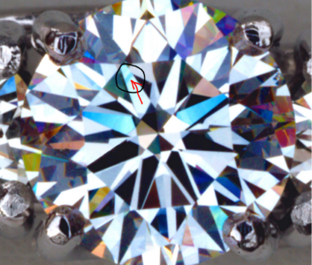
@Garry H (Cut Nut) , would you mind circling the grainy areas you are referring to please? It would be so helpful. Thanks!!
 
@Garry H (Cut Nut) , would you mind circling the grainy areas you are referring to please? It would be so helpful. Thanks!!

In the entire stone picture it is obvious in the blue flash:
1628728455219.png
And in Figure 17 especially - these are not rainbows
1628728531146.png

1628728626877.png
 
A side issue with fire colors. White LED's have little of no violet light at the end of the rainbow (nothing below 430nm) so we miss out on a tiny bit of pleasure now that LED's are taking over the lighting world. Not that anyone would notice.
 
A side issue with fire colors. White LED's have little of no violet light at the end of the rainbow (nothing below 430nm) so we miss out on a tiny bit of pleasure now that LED's are taking over the lighting world. Not that anyone would notice.

This made me sniff outward with laughter - and then try to find new light bulbs.
Thanks for the giggle!
 
Hi Dave,
Thanks for posting. I read through it and hope that it will help some of our readers understand some of the factors that they enjoy when looking at their diamonds.

A couple of points to assist. As John Pollard pointed out in one of his education updates. The transition from dark to blue to bright white to orange to black, or the other way around - black orange white blue black - as we rock a diamond and watch a facet change and flash for our pleasure explains the usual absence of green fire.

Green is joined by orange and indigo paler blue - those three merge into white.

An interesting diversion - it appear Michael's photos in fig 16 and 17 of the dull facets are indicating internal graining in the diamond.
1628724063591.png
The colors in both the right side facets are like the oily water colors you see on a garage floor. They are caused by thin film distortion of light waves.
Here is an example in a stone I saw recently of an intensely grainy diamond.
1628724198213.png
I had sent the above image to one of my retired scientist friends, Grant Pearson, who has time to write long replies:
Morning Garry, I see what you mean, very obvious 'isochromes' development, ie the differential interference colour effects due to internal strain causing ABR, (ie anomalous birefringence), seen normally only between crossed polars. It's sometimes even seen with just a single polar, like when looking at colourless & transparent acrylic or polystyrene plastic mouldings with their inevitable internal strain (arising from differential cooling & contraction), as parallel coloured fringes or patterning while wearing polarising sunnies for instance, or even the peculiar patterning on older car windscreens (modern ones aren't "tempered" with the deliberate inbuilt strain, but are laminated, safer!) or side windows which are still usually of "tempered" or "safety" glass with the deliberate quench strain, & that causes ABR & isochromes development with polarised light, sometimes even visible in just slanted (eg later afternoon) sunlight which is intrinsically partially polarised anyway). Possibly (but probably unlikely?) the colour zones are interference patterns from light reflected between two almost, but not quite, parallel planes, ie facets, that then lead to wavelength-dependent differential interference, just as seen in soap bubbles or films of oil on water puddles after rain, or similar? This effect doesn't require polarisation.


I used the ABR isochrome development polarisation effect successfully some years back whilst consulting for a commercial client in analysing the reasons for breakage of tempered glass components of some gas fueled appliances. A few photomicros are attached just for your amusement of a tiny stressing solidified globular inclusion (fracture initiation location in the tensile zone, shown with "tension halo wings") in a tempered glass item, along with a transmission photomicro also between polars of the actual transparent & polycrystalline inclusion globule (maximum obtainable magnification of the scope) of unknown but birefringent composition, showing intense ABR strain polarisation or interference colours in its different crystal grains,

However, I can't yet explain the cause of the apparent brown colour zoning ("grain") in the illustrated diamond unless they are very thin but planar coloured brown lamellae that appear only in certain orientations, nor the very obvious isochrome development without any polarising light either.

Thanks Grant

Fascinating.

I doubt that the circled facet in Fig 17 is showing interference colours. Note that the dark patches are fringed to the right in orange-red and to the left in blue-purple. This would be typical of prism refraction.

But your diamond picture is fascinating. As your expert says, you can sometimes see interference fringes in flat plastic. The polarization can come from the skylight (strong at 90 degrees to the sun) and from reflection from the plastic. Maybe something like that is happening with your diamond.
 
I will get Mike Cowing to look over the recent postings. I think he will be pleased to gain some additional insights.
 
Michael's article certainly underscores the crucial role that designed-in contrast plays in all aspects of diamond beauty. The whole notion of the positive effects of head shadow can seem a little counter intuitive; why would obstruction of light be a good thing for light performance? This article makes a further contribution to that understanding.

I will have to re-read and compare to the AGS foundational article, but it seems to me Michael puts more emphasis on the role of contrast clipping out some wavelengths and leaving reflections of single colors as the cause of fire, whereas AGS puts more emphasis on the role of the pupil of the eye of the the observer on clipping. Likely both are at play.
 
Something to be learned for those who are curious. Thought it may appeal to some of the participants on the forum.
xxxxxxxxxxxxxxxxxxxxxxxxxxxxxxxxxxxxxxxxxxxxxxxxxxxxxxxxxxxxxxxxxxxxxxxxxxxxxxxxxxxxxxxxxxxxxxxxxxxxxxxxx

Discover the ‘Diamond’s Spectral Constellation’. Michael Cowing explains why the ‘Spectral Constellation’ is the ‘nexus’ connecting a diamond cut’s light performance and its illumination and why it is the key to understanding the occurrence of fire in a diamond when used as a gemstone optical analysis technique.

https://acagemlab.com/ideal-brilliant-cut-and-spectral-constellation/

Michael D Cowing, M.Sc, FGA
AGA Certified Gem Laboratory

Thank you, @oldminer. That article (plus parts 1 and 2 that it referenced) was very rewarding. I now think I understand some things that I didn’t before.

First, how obstruction can produce fire. You can think of the fire as a fringe on the obstruction boundary as viewed through the stone after multiple reflections and refractions. This is why blues and oranges are common (they are the natural fringe colours) but greens are rare.

Next, that the story that fire is produced by spectral fans hitting the eye works for small light sources, but it’s not the whole story.

Next, the amazing sensitivity of diamond performance to minute changes in pavilion angle. Simple reason: for reflections from two opposite mains, changes in the pavilion angle are multiplied by at least 4*r.i. (≈ 10) in the angle of the reverse ray traced exit ray.

The articles definitely helped this diamond newbie
 
Fascinating.

I doubt that the circled facet in Fig 17 is showing interference colours. Note that the dark patches are fringed to the right in orange-red and to the left in blue-purple. This would be typical of prism refraction.

But your diamond picture is fascinating. As your expert says, you can sometimes see interference fringes in flat plastic. The polarization can come from the skylight (strong at 90 degrees to the sun) and from reflection from the plastic. Maybe something like that is happening with your diamond.

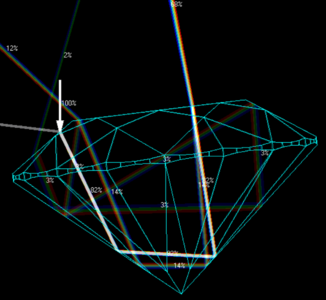
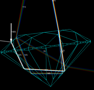
It is possible that the fringing is a result of the 2nd and 3rd exit rays creating those patterns StarStruck. The central region would be exiting to where light is and the higher up portion is also directed right back to the camera lens:
1629069207845.png

1629069253167.png
 
It is possible that the fringing is a result of the 2nd and 3rd exit rays creating those patterns StarStruck. The central region would be exiting to where light is and the higher up portion is also directed right back to the camera lens:
1629069207845.png

1629069253167.png

That's a plausible explanation for the lighter and darker patches (if I'm understanding it correctly). And. on mature reflection, the fringing is entirely to be expected, because the camera is looking through an (outward sloping) kite facet. If this story is correct, it seems that we don't need strain, ADR or the like to explain the patterns.

But your diamond picture is still an intriguing mystery.
 
But your diamond picture is still an intriguing mystery.

This one is very clearly internal stress - it is taken in ViBox with lighting that I had involvement in establishing. There are no tricks.
Light that enters a diamond (or any transparent object) at an oblique angle becomes partially polarized. So what we are seeing is that interaction from the partially polarized light passing through the large emerald cut facets (would not possibly be as apparent in a crushed ice or diamond with smaller facets).
If you look at a table reflection with polaroid sun glasses and rotate the sunglasses you will see bright extinction bright.
1629155177934.png

That makes sense. With oblique incidence, the transmitted light is partially polarized on both entrance and exit, making a (low quality) polarizer and analyser. So in principle you can spot strain. That said, I'm very impressed that it actually works. This one was fun to think about - thank you.
 
This one is very clearly internal stress - it is taken in ViBox with lighting that I had involvement in establishing. There are no tricks.
Light that enters a diamond (or any transparent object) at an oblique angle becomes partially polarized. So what we are seeing is that interaction from the partially polarized light passing through the large emerald cut facets (would not possibly be as apparent in a crushed ice or diamond with smaller facets).
If you look at a table reflection with polaroid sun glasses and rotate the sunglasses you will see bright extinction bright.
1629155177934.png

After some playing with Fresnel’s formula, I have a detailed story about how this could work. Of course, the story may or may not be true :-) Warning: geeky trivia ahead.
DiamondPol.jpg


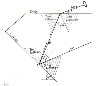
A ray (a) is reflected from a pavilion facet at P as ray (b), then refracted through the table at T to the camera as ray (c). The reflection at P strongly polarizes the light in favour of the parallel polarized component. (At 22.5° incidence, the internal Brewster’s angle, the polarization is perfect. It’s better than 5 : 1 in the range 18.5° to 24°.) Transmission at T moderately favours the perpendicular component. (Polarization is better than 2.5 : 1 for angles from 23° to critical, with a limit of 5.8 ( = r.i. squared) just below critical). So the pavilion and the table act as imperfect crossed polars.

For this story to work at all, the incident angles at the pavilion and the table would both have to be less than critical. (Greater than critical at the pavilion gives total reflection, so no polarization. Greater than critical at the table gives no transmission.) To make the interference colours strong enough to be visible, both incident angles would have to be only slightly less than critical. (Because that makes the polarization strongest.) So the pavilion facet angle would have to be few degrees less than twice the critical angle (≈ 48.9°). This seems plausible for a middle facet of an emerald cut.
 
Great work. Have you accounted for:
1. more than one reflection from the pavilion - there always must be two.
2. except for light entering the pavilion, and in this case there will be some light entering the pavilion because the image was snipped when the stone was slightly tilted.
3. if you reverse the rays you can accounted for losses at first entry point (about 28%)
And finally Mr. Fresnel may be happy but Mr Snell is not.
1629932102959.png
 
Great work. Have you accounted for:
1. more than one reflection from the pavilion - there always must be two.
2. except for light entering the pavilion, and in this case there will be some light entering the pavilion because the image was snipped when the stone was slightly tilted.
3. if you reverse the rays you can accounted for losses at first entry point (about 28%)
And finally Mr. Fresnel may be happy but Mr Snell is not.

Yes, my story has loose ends, mostly because I don’t know the actual shape of your stone or the details of the lighting.

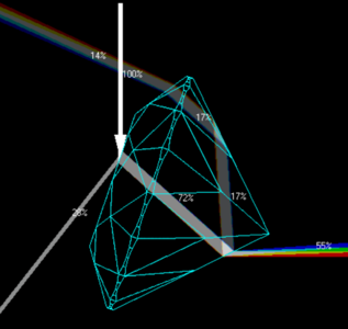
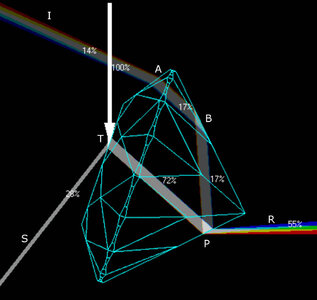
1. Yes. I was thinking of a path like that in your drawing. (I didn’t draw it out because drawing and ray tracing without a program is a pain…) In the forward ray tracing sense, ray I enters at A through a crown facet, is reflected at B from a pavilion facet, then P to S to camera as in my sketch.

Transmission at A will polarize the light in favour of the perpendicular component, which works against my story. But effect is small, because the incident angle is low (ratio less that 1.3 : 1 for incident angles less than 45°.) Reflection at B is total, so it does not change the polarization.

2. Light entering the pavilion at P (ray R in the picture) will be strongly polarized in favour of the perpendicular component, which works against my story. But this may not be a problem. First, I was assuming that the lighting was mostly from above the table (to simulate something like real life). Also, much of the power of ray R, both components, is reflected at P, because the incident angle is high. But still, this is something you would want to check by blocking light from the direction of R.

3. Yes, there is a lot of loss (to reflection) at P. You can’t get strong polarization of the light transmitted at P without high loss. But I’m not seeing that this is a problem for my story. If the camera can see inside the stone at all (as it evidently can), it can only be because of the transmitted light.

A test of the story would be to put a polarizing filter on the camera. If it’s set to pass vertical polarization (i.e. perpendicular to the table) you should see the same colours in the same places, but more intense. If horizontal, they should be inverted.

PolarPicB.jpg
 
@Starstruck8 ,
Your knowledge of the physics of light is very impressive! I'm curious to know something about your background. Judging from your screen name I'm guessing you have some expertise in astronomy?
 
@Starstruck8 ,
Your knowledge of the physics of light is very impressive! I'm curious to know something about your background. Judging from your screen name I'm guessing you have some expertise in astronomy?

First, a typo: in my point 3 above "... a lot of loss of (to reflection) at P. You can't get strong polarization of the light transmitted at P..." Both Ps should be Ts.

Thank you for the compliment. No, I'm not an astronomer, but a lover of star stones - hence my screen name and avatar. My interest in physics is strictly amateur - I like to understand things and I can plug numbers into formulas, but I'm certainly no expert. I'm the little boy who was fascinated by the prisms on my grandmother's antique lustre vases. And now I have grown up and grown old, I can afford to buy expensive little multifaceted prisms...
 
Thank you, @oldminer. That article (plus parts 1 and 2 that it referenced) was very rewarding. I now think I understand some things that I didn’t before.

First, how obstruction can produce fire. You can think of the fire as a fringe on the obstruction boundary as viewed through the stone after multiple reflections and refractions. This is why blues and oranges are common (they are the natural fringe colours) but greens are rare.

Next, that the story that fire is produced by spectral fans hitting the eye works for small light sources, but it’s not the whole story.

Next, the amazing sensitivity of diamond performance to minute changes in pavilion angle. Simple reason: for reflections from two opposite mains, changes in the pavilion angle are multiplied by at least 4*r.i. (≈ 10) in the angle of the reverse ray traced exit ray.

The articles definitely helped this diamond newbie

Thanks Starstruck8, first for taking the time to read and digest all three articles, and second for your response indicating your understanding gained from their reading. Hope it inspires others to do the same. These articles are contributions to the knowledge base of understanding diamond beauty and diamond light performance.

Cheers,
MichaelIdeal + SpectralConstellation.jpg
 
Ideal + SpectralConstellation.jpg

Ever have questions about the Ideal Round Brilliant Cut Diamond?
Then,”Diamond’s Spectral Constellation” is a must read, the last of a three part series that reveals why the small range of angles around the 41 ° pavilion main and 34 ° crown main angles of diamonds graded both AGS 0 Ideal and GIA Excellent have not been surpassed in beauty and light performance in over a century and a half.

Discover the ‘Diamond’s Spectral Constellation’. Michael Cowing explains why the ‘Spectral Constellation’ is the ‘nexus’ connecting a diamond cut’s light performance and its illumination, and why it is the key to understanding the occurrence of fire in a diamond when used as a gemstone optical analysis technique.

https://acagemlab.com/ideal-brilliant-cut-and-spectral-constellation/

Clicking on this url and then Diamond’s Spectral Constellation takes you to the adobe digital publication.

Double clicking on any pair of pages doubles the page size for easy reading. At the bottom right of the screen are useful icons, one for downloading a printable pdf of each article.

The three articles are found at https://acagemlab.com/category/diamonds/cut-beauty-light-performance/

The classic round brilliant cut diamond evolved to become the universally most popular style of cutting; bringing out the best in diamond’s ‘light performance’, meaning its greatest beauty.

Ideal was the term used since the early 20th century, for the range of angles and proportions of the brilliant cut found to maximize the attributes of diamond beauty; brilliance, fire and scintillation. Early writers and cutters defined the ‘Ideal Cut’ in terms of the pavilion and crown main facet angles. Of seven parameters defining the round brilliant cut, this pair of angles is most critical to round brilliant light performance. Of the remaining parameters, pavilion half length or angle, is most important, followed by table %, star length, girdle thickness, and culet size. These parameters are cut in relation to the pavilion and crown main angle combination. The important angle of the pavilion halves is cut close to the pavilion main angle (most often within 1.4°).

All seven parameters are measured and included in today’s definitions of the best or Ideal grades. Only a small range of the main angle combinations may receive both the AGS 0 Ideal grade in the system of the American Gem Society (AGS), and the ‘Excellent’ grade in the cut grading system of the Gemological Institute of America (GIA). Ideal, in these articles, refers to this small range of best crown and pavilion main angle combinations. These key angles are shown to result in the best round brilliant beauty/light performance.

Going back over 100 years, numerous efforts have been made to analytically prove the superiority of the small range of angles called Ideal. Several metrics and methods have been developed in attempts to provide this proof. Ray tracing was employed by many, Marcel Tolkowsky, for instance, in his 1919 book, ‘Diamond Design’ made extensive use of ray tracing to develop his theoretical best angles. Others developed measures of aspects of diamond beauty, such as brilliance and fire, including, in the United States, the grading laboratories of the GIA, and the AGS.

It is problematic that metrics most often fail to point to why this small range of key angle combinations is best. Instead, most metrics of brilliance and fire show peaks or maxima well away from the narrow range graded Ideal and Excellent.

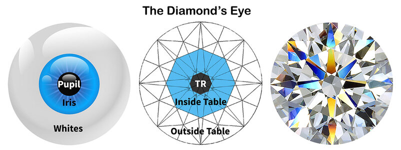
These three articles provide answers to why the Ideal Cut’s small range of angles is best. Techniques including reverse ray tracing, "spectral constellation" analysis and analytical lighting and photography are used to provide an understanding of diamond light performance. An important element of this analysis is the concept of the ‘diamond’s eye’. Together, these analysis techniques are employed to explore the range of angles found to be the best or Ideal by GIA Laboratories (the Excellent grade); by AGS Laboratories (the AGS 0 Ideal); and by diamond cutting schools and institutions and the author. Negative light performance effects ensue when a diamond is cut outside of this range of best angles. These are explored and analyzed in this trilogy of articles.

Cheers,

Michael
 
Thank you, michaelgem - your articles are fascinating and extremely helpful!
 
Comments from the USFG faceting community:
Aaron Matthew Hubbard comments:
I’m of the opinion that if you could dop up a diamond like a colored stone and cut it, that opinion of the SRB being the “brightest best cut” would go bye bye.

Michael: should have made clear that these three articles are about the best or Ideal small range of angle combinations of the SRB, not of any other cut or modified brilliant. Within the context of the SRB angles and proportions, these articles provide answers to why the Ideal Cut’s small range of angles and proportions are superior in beauty and light performance to diamonds cut with parameters outside these best ranges.

Aaron Hubbard : It’s been talked about and settled for the hundred and fifty years your post talks about….Again.

Aaron, it’s been talked about and largely settled in the minds of top diamond cutters like Basil Watermeyer going all the way back to 1860 and the Boston diamond cutter, Henry Morse, who first cut to what is now known as Ideal angles for diamond.

But, as said before, even GIA researchers concluded “they do not support the idea that all deviations from a narrow range of crown angles and table sizes (called Ideal) should be given a lower grade”.

Going back over 100 years, numerous efforts have been made to analytically prove the superiority of the small range of angles called ‘Ideal’ that today receive cut grades of Ideal and Excellent. Several metrics and methods have been developed in attempts to provide this proof. Ray tracing was employed by many (e.g. Marcel Tolkowsky in ‘Diamond Design’). Others developed measures of aspects of diamond beauty, such as brilliance and fire, including, in the United States, the grading laboratories of the GIA, and the AGS.

It is problematic that metrics most often fail to point to why this small range of key angle combinations is best.

Many, like the renowned diamond cutter, Basil Watermeyer likely would point out that this ideal range was found by members of the diamond cutting profession by “cut and try” over more than a century. No proof needed. However, efforts to analytically prove the Ideal’s superiority using measures of brilliance and fire have largely fallen short. Consequently, the effort to provide these answers remains interesting and meaningful.

It is rightly said that there are diamond cut deviations from the Ideal that are beautiful, especially in favorable lighting circumstances. However, it is also true that significant deviations outside the small range graded Ideal and Excellent are seen in comparative testing to have light performance inferior to Ideal. And the poor light performance of the fish-eye or the nailhead is encountered within just three degrees deviation from the central ideal angle combination of (41°, 34°).

These three articles provide answers, not previously published, and largely unknown to the industry, as to why the Ideal Cut’s small range of angles and proportions are superior in beauty and light performance to diamonds cut with parameters outside these best ranges.
 
Finally had a chance to give all three articles a good read. I think it's an excellent set of articles that provides a technical understanding of why diamonds cut to very tight tolerance around the 'Central Ideal" exhibit optimal light performance.

His explanations about reverse ray tracing, virtual facets, the critical role played by the observer in creating positive contrast, and the importance of that dynamic contrast to all aspects of diamond beauty, is some of the most digestible I have seen.

Some of this is not exactly 'beginner' material, but the author succeeds in making it accessible to interested intermediate level enthusiasts. I would also highly recommend it to trades people who have not yet availed themselves to technical learning about cut quality and light performance. (and there are a lot of them!)

I particularly like the homage Cowing pays to the early American diamond cutters who had already figured out ideal parameters (and were actively promoting cutting for beauty over weight) well before Tolkowsky wrote his famous work and was essentially coronated as father of the ideal cut.

I was a little surprised, in the context of explaining the importance of the 34c/41p combo, that there was not mention of the importance of facet precision. Especially since emphasis was rightly put on the importance of the proper mix of larger and smaller virtual facets. Without optical precision, the very facet design prescribing that mix is undermined.
 
Last edited:
Also, I think the concept of the "Diamond's Eye" is instructive. And I don't remember ever reading as thorough a discussion of the table reflection. And it is a source of frequent questions.
 
Great review Bryan. You mentioned several important concepts and ideas, like the Diamond's eye, covered in these three articles. You also pointed out that the importance of optical symmetry was not discussed. Did not want to add that complexity to these three articles. I think it deserves its own separate discussion. Lack of optical symmetry in the mains results in further break up of light, increasing scintillation, but reduces the large flash brilliance and fire we expect from the reflections coming to our eyes due to the mains.

Is there a place anymore for contributed articles like these 3 pdf's where they would not age, and portions of them could be referred to in future discussion? Be nice to hash over some of the concepts, like the diamond's spectral constellation, and the diamond's eye, in separate posts and discussions. Might encourage more interest in all the issues addressed.

Thanks for your review,
MichaelFigure 6 Latest Eyeofthediamond with caption.jpg
 
I would encourage pricescope to find a place for these articles in their knowledge base so they can easily be accessed by the community here and referenced for future discussions.
@John Pollard is now director of education for pricescope so he may be able to consider it.
 
GET 3 FREE HCA RESULTS JOIN THE FORUM. ASK FOR HELP
Top