shape
carat
color
clarity

What A Scanner Sees

Status
Not open for further replies. Please create a new topic or request for this thread to be opened.

beryl

Shiny_Rock
Joined
Nov 6, 2003
Messages
288
This will repeat material that got lost at the end of another thread, among unrelated conversation between other members. It is too important to get lost like that.

I don't yet know how diamond scanners work, but this shows what they see if looking at a profile, as in a 'shadowgraph' machine used in industry for inspection, or the old GIA ProportionScope.
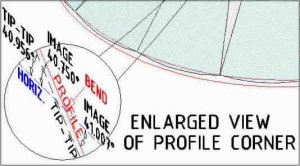
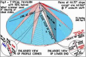
Here is a pic of what a scanner sees if viewing a profile according to the direction of the ideal index, when a main has been cut at a shifted azimuth. In this example one main was cut at 1° from ideal index (or azimuth), and therefore at a steeper slope (40.960°) to maintain the same join with the neighboring main on its left side.
In this case the scanner will see the left edges of the main, which show a bend in the profile (red) on the image plane - see enlarged view at lower left. The upper segment (join between mains) is still at 40.75° (because the slope of the twisted facet was chosen to maintain this edge of the ideal cut), but this is not the slope of the main in question. The lower segment is at slope of 41.007°, which is also a false indication.
On the other hand, if the scanner looks only at the top and bottom end of the facet, and assumes a straight line between them, it would say 40.956° if it could measure that accurately, which would also be a false indication.
Only if the scanner looks at the actual 1°-shifted index, parallel to its trace (red line in girdle plane), will it see a straight profile and the true slope - by profile and/or tip-to-tip - of 40.960°.
Is this significant? That's for you to decide. I think that one decimal place is suitable for reports, in which case 40.960°, 40.956° and 41.007° would all round-off to 41.0°. The 40.75° indication would be unacceptable and the machine or user would have to ignore it.
yaw8y.jpg
 
Here is a blowup of the lower left enlargement.

yaw8ax.jpg
 
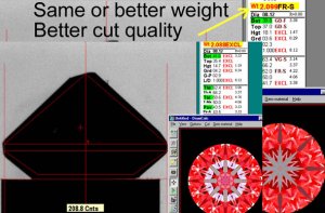
Beryl i am afraid i do not have a scan of a polished piece of rough, but this image from a Lexus scanner of a bruted stone in planning for blocking should suffice.

The scanners have controls that allow selection of accuracy. Sarin typically run on about 100 photo''s for 360 degrees of rotation. The information from the photo''s is processed to build a feasible 3D model made up of ''closed'' flat facets. The scanner software likes to be told what shape of stone it is scanning, then it can "average" out the data and build a model with 57/58 facets in the case of a round brilliant.

BUT - this means the model is made by using algorithms that make the stone more symmetrical than it possibly is.

Solution - run a larger number of scans - Helium lets the user easily make a selection between 100, 200, 400 and even 800, with obviously more photo''s = better accuracy, but more time per scan.

There are critical debates as to how hard the softwares algorithms should work to ''build'' a model. We know from just looking at Ogi screens, they do a lot of work by adding extra little junctions at facets on the crown to make the models ''closed'' physical objects. Helium has algorithms too, but they are less likely to reduce the accuracy of the model when compared to the real diamond.

LexusProfile.jpg
 
Beryl: You are making quite a compelling case for not using scanners to make measurements in order to utilize ray or beam tracing for the prediction of light performance. Scanners are best utilized to make cutting recipes.

As many of you are aware, I am an advocate of direct measure of light performance. This does not mean prediction of light performance is invalid, but just that it is not accurate as alternative methods. Cutters do need predictive tools, but consumers want to know about their stone to the highest degree of certainty we can give them.
 
Hey Bruce,

Thanks for this post. If I may pose some questions for sake of clarity.


This will repeat material that got lost at the end of another thread, among unrelated conversation between other members. It is too important to get lost like that.

If its the thread I''m thinking I would like to bring closure to that thread too Bruce but without all the testosterone that was being flung around. I think there was alot of good information to come out of that and planned on bringing some closure there. I''m actually working on a letter now but was going to review it one last time before final edit. As I sit and read and study your illustrations, questions pop up and things are learned. This is good.


I don''t yet know how diamond scanners work, but this shows what they see if looking at a profile, as in a ''shadowgraph'' machine used in industry for inspection, or the old GIA ProportionScope.

Is it even fair to compare that old GIA proportion scope with the advanced scanners available now? Before we had a Sarin I used to use that old ... dinosaur. :) Served me well while we had it but to attempt to measure pavilion angles down to .0001 degrees on it or azimuth shift ...
3.gif
A cold day in hell.

Are you saying that a Sarin/OGI or even Helium has the same identical measuring abilities as the old GIA proportionscope Bruce? Ie. they both use a silouhette therefore are measuing the same?


Here is a pic of what a scanner sees if viewing a profile according to the direction of the ideal index, when a main has been cut at a shifted azimuth. In this example one main was cut at 1° from ideal index (or azimuth), and therefore at a steeper slope (40.960°) to maintain the same join with the neighboring main on its left side.
In this case the scanner will see the left edges of the main, which show a bend in the profile (red) on the image plane - see enlarged view at lower left. The upper segment (join between mains) is still at 40.75° (recall that the new slope of the twisted facet was chosen to maintain this edge of the ideal cut), but this is not the slope of the main in question. The lower segment is at slope of 41.007°, which is also a false indication.
Please correct me if I''m wrong but you are saying that there is one pavilion main facet, azimuth or index shift at 1 degree. Because of this, THIS MAIN will necessarily be at a steeper angle (assuming all other pavilion mains are at 40.75 degrees). On the main that''s twisted you are saying that the top of that facet measures 40.960 while the bottom is 41.007 ... a difference of .047 degrees from top to bottom. Now THATS a frog hair.
3.gif
So in short you are saying ...

a. A twisted pavilion main facet will of necessity be steeper than the rest of the neighboring pavilion main facets.
b. The main that was twisted will have a different slope angle at one end of the facet than the other. In this case a difference of .047 degrees.

Please correct me if I''m wrong.

I''ll try this in DiamCalc and see if it corresponds. While I am at an infancy stage in my research on azimuth angles with Helium I have not specifically located a diamond with a main that is shifted to this degree. Would it matter if the main was shifted to the east or west or would the results be the same either?


On the other hand, if the scanner looks only at the top and bottom end of the facet, and assumes a straight line between them, it would say 40.956° if it could measure that accurately, which would also be a false indication.

Ok... when I take the top of that facet at 40.960 and I add the bottom to that of 41.007 that gives me an average of 40.9835 degrees.

How did you arrive at 40.956?

Assuming my math is correct I think I see where you''re heading with this. You are approaching this from an entirely different angle than I am Bruce and I can appreciate that. You are concluding ... if a scanner can''t detect this difference of .047 degrees due to the shift in azimuth angle then how can anyone even make the claim to observe and photograph it? Is this the question?
2.gif
If so, I have the answer.
9.gif
If not, disregard and I''m reading something into this you did not intend.


Only if the scanner looks at the actual 1°-shifted index, parallel to its trace (red line in girdle plane), will it see a straight profile and the true slope - by profile and/or tip-to-tip - of 40.960°.
Is this significant? That''s for you to decide. I think that one decimal place is suitable for reports, in which case 40.960°, 40.956° and 41.007° would all round-off to 41.0°. The 40.75° indication would be unacceptable and the machine or user would have to ignore it.

I think this is what Paul was asking me for in May. It took this long to figure-out how to illustrate it
While I have not specifically tested stones with shift in azimuth on the pavilion mains yet, I''ve started, by necessity with what I have here in my lab, one with shifts in the lower halves. At my earliest convenience I''ll sit with DiamCalc and try your example by twisting one of the mains 1 degree and study its effect on the optical signature. Then I''ll see if I can find one here in our store and compare and photograph it for you to compare to the optical signature shown with DiamCalc. I have found amazing consistency between the images it generates based on the scans from Helium vs our photography of the same phenomena. Garry and Serg have both noted this as well and we have discussed this in email before. We were photographing the phenomena before it was even showed as a default in the DiamCalc software. Garry & Sergey will attest to this. I love the dialogue beryl and look forward to continuing with ya.

Warm regards,
 
Interesting Garry.

This begs the question ... how can the accuracy of a scanner be determined?

One solution (among others) ...

a. Photograph the optical signature of the actual diamond and capture the most detail of that signature possible.
b. Compare that to the image generated by the model produced by the scanner under the same illumination environment.
c. Compare and contrast the images.
d. The photo will *always* win out over the model because the diamond IS THE REAL DEAL. The model is the best that technology can offer.

Edited to add: The photo MUST DUPLICATE exactly or NEAR exactly the illumination environment generated withiin DiamCalc. If it doesn't the photograph will be inaccurate.

This is one way we test the accuracy of a scanner amongst others.

When I get on my other laptop I have models generated with Helium which I've created DiamCalc files for and actual photographs of the diamonds optical signature.

The resemblance will absolutely astound you Garry. What will blow you away further is when you consider the numerical data (ie. shift in azimuth angles). If you like I'll post the example I used in the "New Teaching" thread as this was a test subject for my study. What say? Does this interest you? If so I'll also email all of you the DiamCalc file generated by Helium for observation and confirmation and then you can tell me ... Rhino you're right on or Rhino, you're off your rocker.
9.gif
If not and you guys feel I'm hijacking this thread and taking it in a direction that was not intended I woud like to apologize and bow out now. I know beryl is posting things in response to the other thread, *I think* I know where he was headed but I could be mistaken and if I am I apologize for that and just wait for beryl's response.

I am excited about the new research we are conducting but at the same time I don't want to appear to be bragging or a pompous ass about it too. I respect all the players here. I've learned a valuable lesson this week on "the delivery" and I am not looking to lose anyone's respect by sharing it, so I apologize in advance if you think I am skewing this thread and will bow out to let you guys continue the conversation. These were just the natural questions and thoughts that came to mind as I was reading.

Kind regards,
 
Bruce I think you are saying that unless the shadow edge is viewed in perfect profile, the 3D model will be wrong.
As well as my answer above, and as Sergey mentioned in anther thread, the algoritms build a closed model - one without virtual air gaps or overlapping facets. The data gets used creatively based on an assumption of flat facets.

In Brian''s yaw examples he has told me the facets remain flat. So there appears to be no reason from that perspective why we should be discussing curved facets?

Scanners assume the facets are flat. Bruce you are introducing curved facets. Scanners will have a problem with a facet that has 0.2 degrees of curvature. But is this realistic? I do not believe I have ever seen a curved facet on a diamond?
 
I had been asked how a scanner measures a 'yawed' facet. I was trying to answer that.

I said that I do NOT know how scanners work, but IF they look at a shadow profile, as in a 'shadowgraph' or ProportionScope, this is what they will see. If this is not how they work ignore the rest.

If not viewed parallel to the main, they would see a bent line which is a projection of the joins of this main with its neighbors = 2 different 'slopes' (40.750° and 41.007° in this example).
In another thread someone said that one maker measures the tips and assumes a straight line (not bent) between them, to circumvent another's patent. That simulated value is calculated as a straight line between these points (40.956° in this example); it is not an average of two other values.

I think that all of this is clearly stated in the text and illustrations.
There are no curved facets in this study. It has nothing to do with rough or bruted stones.

Using AutoCAD I was able to construct and measure these angles precisely on this diagrammatic model; it is quite tricky to do so; AutoCAD measures the angles, I do not. If this is not how scanners work then it is academic. The precision I showed is silly in the real world but used here only to show the differences. As stated, I think that one decimal place is adequate for any report.
 
re: Only if the scanner looks at the actual 1°-shifted index, parallel to its trace (red line in girdle plane), will it see a straight profile and the true slope - by profile and/or tip-to-tip - of 40.960°.
Is this significant? That''s for you to decide. I think that one decimal place is suitable for reports, in which case 40.960°, 40.956° and 41.007° would all round-off to 41.0°. The 40.75° indication would be unacceptable and the machine or user would have to ignore it.
Wrong.
Bruce,
Helium algorithm is much more complex than simple idea had been described by you.


Rhino,
please do next test for Bruce.
1) Put round stone to Helium
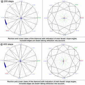
2) Scan this diamond in same position by two methods Accuracy( 400 photos , 0.9 degree step) and Optimum ( 200 photos , 1.8 degree step)
3) Print slope angles for main facets for both methods.

 
Date: 9/11/2005 7:35:51 PM
Author: oldminer
Beryl: You are making quite a compelling case for not using scanners to make measurements in order to utilize ray or beam tracing for the prediction of light performance. Scanners are best utilized to make cutting recipes.

As many of you are aware, I am an advocate of direct measure of light performance. This does not mean prediction of light performance is invalid, but just that it is not accurate as alternative methods. Cutters do need predictive tools, but consumers want to know about their stone to the highest degree of certainty we can give them.
Dave,
BTW I did not receive any answer from Imagem or you for next my comments and questions:
Next features could indicate problems of system:
1) Different metric for different cuts
2) Absence correlation of grade form size diamond. Is any current direct system could show next correlation :
Small( 0.1 ct) diamond should has less number of facets than Big( 5ct) diamond?

Below are my next very important questions to Imagem:
What diamonds had been use for training Sophisticate Intelligent software and what diamonds had been use only for verification result of such training.?
Who and How did grade beauty, Scintillation, brilliancy of diamonds for training and verification?

Hardware, software could be closed for protection investment.
But information about collection diamonds for training and verification should be published.
I see only one reason for hiding such information - Had been used convenience sample of diamonds.
Could you show other reason?
 
Does anyone mind if I add to the confusion?

Even though the following may sound off topic, it is not.

Most of you know that I am an afficionado of cycling, and I love it when I can use it in an example. Now imagine a broad road uphill with a slope of 15%. At some point in time, now years ago, it was not a problem to drive up that road in a straight manner.

Nowadays with higher age (although not really old) and especially less practice, I will need to zigzag.

This is a clear example of how the slope of that road is lower if one would drive from the right hand side at the bottom up to the left hand side at the top.

And for Garry''s sake, I just want to confirm that the road is not curved.

Beware, there is a lot of food for thought in this example. If I take it a few steps further, I realise that there is a gap in the way ''light refraction'' was taught to me in my gemmology-class.

Live long,
 
Sergey; I want ImaGem to respond to you and have copied your message to Dr. Aggarwal. I trust they will respond. A response from me would likely be inadequate. I think your questions are valid ones and deserve consideration by experts. Thank you for your patience.
 
Dave, Thanks.
 
Serg: What does your discussion with Dave re Imagem have to do with this thread?

Paul: I suspected that this what you and Brian were talking about; your analogy removes all doubt.
As in your bicycle ride we can draw lines at any direction on the road up the side of the hill, but only the steepest direction (a family of parallel lines) is called the 'slope'. Ask any cilvil engineer involved in road building (they measure slopes as ratios or percentages, such as 1:4, or 25%, not angles - that would be 14° in this case).
In faceting, 'slope' is the angle between the dop axis and the axis of the lap, or 'scaife'. It is also the angle between the facet and the girdle plane - measured in a plane perpendicular to those two surfaces.
The steepest angle = "slope" can be found by drawing a line from any point on the facet, such as its upper tip, perpendicular to the 'trace' (the line where the facet intersects the girdle plane). Draw another line in the girdle plane which is also perpendicular to the 'trace' at the same point and the angle between them is the 'slope'.
In the case of a 'yawed' main this slope line may not go from one tip to the other. In Fig.8 the line drawn from tip to tip was not perpendicular to the trace, so its angle to the girdle plane was less than the actual slope, like your angular bike path.

I don't expect everybody to follow this. I have done my best.

Edit 6:45 PM: Paul; I meant to mention another analogy: If you let a liquid flow slowly down an incline it will follow 'the line of steepest descent' - that would be the 'slope' of a flat (not level) surface.
 
Date: 9/12/2005 5:17:28 AM
Author: Serg

re: Only if the scanner looks at the actual 1°-shifted index, parallel to its trace (red line in girdle plane), will it see a straight profile and the true slope - by profile and/or tip-to-tip - of 40.960°.
Is this significant? That''s for you to decide. I think that one decimal place is suitable for reports, in which case 40.960°, 40.956° and 41.007° would all round-off to 41.0°. The 40.75° indication would be unacceptable and the machine or user would have to ignore it.

Wrong.
Bruce,
Helium algorithm is much more complex than simple idea had been described by you.


Rhino,
please do next test for Bruce.

1) Put round stone to Helium
2) Scan this diamond in same position by two methods Accuracy( 400 photos , 0.9 degree step) and Optimum ( 200 photos , 1.8 degree step)
3) Print slope angles for main facets for both methods.

As soon as I get up to work tomorrow I''ll have this posted.
 
Date: 9/12/2005 6:02:50 PM
Author: beryl
Paul: I suspected that this what you and Brian were talking about; your analogy removes all doubt.
As in your bicycle ride we can draw lines at any direction on the road up the side of the hill, but only the steepest direction (a family of parallel lines) is called the ''slope''. Ask any cilvil engineer involved in road building (they measure slopes as ratios or percentages, such as 1:4, or 25%, not angles - that would be 14° in this case).
In faceting, ''slope'' is the angle between the dop axis and the axis of the lap, or ''scaife''. It is also the angle between the facet and the girdle plane - measured in a plane perpendicular to those two surfaces.
The steepest angle = "slope" can be found by drawing a line from any point on the facet, such as its upper tip, perpendicular to the ''trace'' (the line where the facet intersects the girdle plane). Draw another line in the girdle plane which is also perpendicular to the ''trace'' at the same point and the angle between them is the ''slope''.
In the case of a ''yawed'' main this slope line may not go from one tip to the other. In Fig.8 the line drawn from tip to tip was not perpendicular to the trace, so its angle to the girdle plane was less than the actual slope, like your angular bike path.

I don''t expect everybody to follow this. I have done my best.

Edit 6:45 PM: Paul; I meant to mention another analogy: If you let a liquid flow slowly down an incline it will follow ''the line of steepest descent'' - that would be the ''slope'' of a flat (not level) surface.
Hi Bruce,

You definitely understand me.

My follow-up question is in the gemmological field: in the theory of light refraction, we work with the slope of a facet. Forget about yaw or azimuth change, for a second, my question also applies to facets, cut in a straightforward manner.

However, there are multiple angles in a facet, perpendicular to all kinds of incoming angles.

My question may be utterly stupid, but my thinking is blocked by the question, and I need someone to help me get rid of it: Is it correct to calculate on the basis of the slope only, while there are so many multiple angles at play? Why?

Live long,
 
Date: 9/13/2005 10:07:33 AM
Author: Paul-Antwerp
Date: 9/12/2005 6:02:50 PM


My question may be utterly stupid, but my thinking is blocked by the question, and I need someone to help me get rid of it: Is it correct to calculate on the basis of the slope only, while there are so many multiple angles at play? Why?


Live long,
Awesome question Paul and one that is not stupid at all.
That would tie back to the performance issues of the other angles.
Its a question that needs solid research.
Id love to hear the answer because it would answer if azimuth shift and yaw is a make issue or a performance issue.
 
Date: 9/13/2005 10:07:33 AM
Author: Paul-Antwerp

Date: 9/12/2005 6:02:50 PM
Author: beryl
Paul: I suspected that this what you and Brian were talking about; your analogy removes all doubt.
As in your bicycle ride we can draw lines at any direction on the road up the side of the hill, but only the steepest direction (a family of parallel lines) is called the ''slope''. Ask any cilvil engineer involved in road building (they measure slopes as ratios or percentages, such as 1:4, or 25%, not angles - that would be 14° in this case).
In faceting, ''slope'' is the angle between the dop axis and the axis of the lap, or ''scaife''. It is also the angle between the facet and the girdle plane - measured in a plane perpendicular to those two surfaces.
The steepest angle = "slope" can be found by drawing a line from any point on the facet, such as its upper tip, perpendicular to the ''trace'' (the line where the facet intersects the girdle plane). Draw another line in the girdle plane which is also perpendicular to the ''trace'' at the same point and the angle between them is the ''slope''.
In the case of a ''yawed'' main this slope line may not go from one tip to the other. In Fig.8 the line drawn from tip to tip was not perpendicular to the trace, so its angle to the girdle plane was less than the actual slope, like your angular bike path.

I don''t expect everybody to follow this. I have done my best.

Edit 6:45 PM: Paul; I meant to mention another analogy: If you let a liquid flow slowly down an incline it will follow ''the line of steepest descent'' - that would be the ''slope'' of a flat (not level) surface.
Hi Bruce,

You definitely understand me.

My follow-up question is in the gemmological field: in the theory of light refraction, we work with the slope of a facet. Forget about yaw or azimuth change, for a second, my question also applies to facets, cut in a straightforward manner.

However, there are multiple angles in a facet, perpendicular to all kinds of incoming angles.

My question may be utterly stupid, but my thinking is blocked by the question, and I need someone to help me get rid of it: Is it correct to calculate on the basis of the slope only, while there are so many multiple angles at play? Why?

Live long,
Hi Paul,

Excellent and interesting analaogy. I trying my best to follow along here.

If I am, with any success, peering into your mind ... you''re saying that while slope angles are measured against the girdle plane, there are, in reality many angles that come into play regarding the optical properties of a diamond. Ie. Let''s take one pavilion main for a second. Say it''s 40.75 in relation to girdle plane ... however since reflections off that main impact reflections off the opposite corresponding main, there is a relationship between the angles of those 2 facets that don''t necessarily relate to the girdle plane.

Am I following you correctly?
33.gif
If not, please expound.

I really enjoy the conversation and Bruce, by no means are your posts in vain. I can''t begin tell you how much I appreciate your posts. When we get together dinner is on me.
21.gif
 
Date: 9/13/2005 10:15:29 AM
Author: strmrdr

Date: 9/13/2005 10:07:33 AM
Author: Paul-Antwerp

Date: 9/12/2005 6:02:50 PM


My question may be utterly stupid, but my thinking is blocked by the question, and I need someone to help me get rid of it: Is it correct to calculate on the basis of the slope only, while there are so many multiple angles at play? Why?


Live long,
Awesome question Paul and one that is not stupid at all.
That would tie back to the performance issues of the other angles.
Its a question that needs solid research.
Id love to hear the answer because it would answer if azimuth shift and yaw is a make issue or a performance issue.
strm... we are thinking along the same lines here I believe. We''ll wait for Paul''s answer to confirm. If we are indeed on the same page I believe I may have some answers to these questions, at least with regards to performance issues. At the AGS/GIA lab level I don''t think they would give a strike to a stone for either make or performance, but discussing this in the depth or at the level we are discussing here Paul and Bruce *may indeed* consider this a make issue. We''ll wait for more.
34.gif
 
Serg ... as per your request.

I used a stone that's not one of our typical stones but one with larger deviations between the mains. Note: For any layman following this dicussion the blue shown just under the pavilion main at 9:00 is an extra facet on that stone and is constructed identically to the model and printed report shown here in case you were wondering what that funny shape was there. :P

Peace,

precisiontest02.gif
 
Rhino Thanks.

Bruce,

I hope you there is at least one pavilion main facet with distance from nearest contour bigger than 1 degree for test with 200 contours.
But difference between slope angle between 200 contours model and 400 contours model <=0.01 degree( much less than 0.047)
 
Date: 9/13/2005 11:39:56 AM
Author: Rhino

Hi Paul,

Excellent and interesting analaogy. I trying my best to follow along here.

If I am, with any success, peering into your mind ... you''re saying that while slope angles are measured against the girdle plane, there are, in reality many angles that come into play regarding the optical properties of a diamond. Ie. Let''s take one pavilion main for a second. Say it''s 40.75 in relation to girdle plane ... however since reflections off that main impact reflections off the opposite corresponding main, there is a relationship between the angles of those 2 facets that don''t necessarily relate to the girdle plane.

Am I following you correctly?
33.gif
If not, please expound.

I really enjoy the conversation and Bruce, by no means are your posts in vain. I can''t begin tell you how much I appreciate your posts. When we get together dinner is on me.
21.gif
Sorry Rhino,

You are not following me correctly. We are not even close to discussing the opposite facet, this is still about the first facet.

Sorry, I cannot expand further now. I have to run for an appointment.

Live long,
 
Date: 9/13/2005 1:12:43 PM
Author: Serg

Rhino Thanks.

Bruce,

I hope you there is at least one pavilion main facet with distance from nearest contour bigger than 1 degree for test with 200 contours.

But difference between slope angle between 200 contours model and 400 contours model <=0.01 degree( much less than 0.047)
re:distance from nearest contour bigger than 1 degree for test with 200 contours.

Sorry such distance can not be bigger than 0.9 degree for step 1.8 degree.

0.7 is resonable( each angle is from 0 to 0.9)
 
Paul:
Slope has nothing to do with reflection.
A ray approaches a surface. Only one plane can be drawn through the ray which is perpendicular to the surface. When the ray is reflected and/or refracted it continues in the same plane - the reflection at the same angle back away from the surface, the partial refraction, if any (other factors involved here). will also continue in the same plane but at a different angle on the other side of the surface. This is in any basic optics text
Gotta run. Will make simple pics at casino tomorrow.
 
Date: 9/13/2005 3:48:47 PM
Author: Garry H (Cut Nut)
Sergey I do not understand your point?
Garry,

Did you understand Bruce point?
 
Date: 9/13/2005 3:48:47 PM
Author: Garry H (Cut Nut)
Sergey I do not understand your point?

Date: 9/13/2005 3:48:47 PM
Author: Garry H (Cut Nut)
Sergey I do not understand your point?
Just catching up here. ... Reading where I had left off ... reading Paul's post
33.gif
... readings Sergey's post ... pondering ...
33.gif
" then reading your comment made me crack up cause I felt real stupid but see I'm not alone.
9.gif
 
Bruce will correct me if I'm mistaken but I think he's trying to continue a conversation that had begun in another thread which has kinda went back now around 3-5 pages ago on the minor facets started by Midnight. The thread eventually became a very hot topic on the subject of azimuth angles and yaw. Brian and John (along with Bruce's initial graphic demonstrating the technics of it) did what is perhaps is the best presentation of it that could ever be given. Only it didn't sink into the heads of some fully (including myself) until reading and thinking about it for some time. When John and I had first discussed the topic I thought I was understanding his view, especially with regards to yaw east/west shift in a main. If you take note of John's graphic's in that thread he actually (whether he realizes this or not) discusses two elements regarding yaw.

One being the physical shift in the facet ... pushing the main if you will, and in another graphic he demonstrates a yaw in light path ... if I am understanding him correctly ... a yawed or skewed light path that results from the physical yaw. Correct me if I'm wrong John but I am really trying to comprehend this stuff and its easy to understand how one could confuse the two or even the issue.

In any case, the reason I was excited about this on a personal level is because it relates directly to my studies on the optical signature of a diamond. This is my life and passion. I observe and photograph east west shifts every day, I just never had the means by which to explain the phenomena I've been photographing. That's all. I admit I had trouble grasping the physical yawed concept ... cutters would understand that 100x more than me, but when we're talking about yawed light path ... I can relate to that 100%. This relates directly to "direct assessment of light reflections" through the crown. My speciality!

I *think* Bruces point (and by all means correct me again if I'm wrong
40.gif
), perhaps may have been to suggest that scanners, based on measurements taken from a silhouette (like the old GIA Scope, Helium/Sarin/OGI) can not accurately see azimuth deviation from ideal or yaw or perhaps both. I realize this takes a little reading between the lines and also that I may be totally off here (LOL ... me kicks myself in the ass if I am
3.gif
) which brings us exactly where we left off in the other thread ... burden of proof on me ... and the ability of Helium to do exactly what we are claiming.

I realize this conclusion sounds very selfish and self centered and I apologize if I am being perceived in this light but Bruce ... am I even close?
33.gif
9.gif
I see I've misunderstood Paul's point about a facet being examined from many angles (I was thinking angles in relation to girdle plane as opposed to angles in relation to each other ...) but from what I'm putting together from recent threads this is what I am extracting. A kind challenge?
1.gif
Ok ... everyone get their tomatoes ready.
41.gif
23.gif


Bruce, if I am correct give me one of these ...
36.gif
, if I'm close one of these ...
12.gif
(for effort), if not, one of these...
38.gif
. If the first I'll present the proof you seek and we can continue the discussion here in this thread.

Edited to add: I think I realize that you are attempting to bring closure to the conversations that were taking place on that thread. If so, I thank you.

Kind regards,
 
Date: 9/14/2005 12:03:14 AM
Author: Rhino
Bruce will correct me if I''m mistaken but I think he''s trying to continue a conversation that had begun in another thread which has kinda went back now around 3-5 pages ago on the minor facets started by Midnight. The thread eventually became a very hot topic on the subject of azimuth angles and yaw. Brian and John (along with Bruce''s initial graphic demonstrating the technics of it) did what is perhaps is the best presentation of it that could ever be given. Only it didn''t sink into the heads of some fully (including myself) until reading and thinking about it for some time. When John and I had first discussed the topic I thought I was understanding his view, especially with regards to yaw east/west shift in a main. If you take note of John''s graphic''s in that thread he actually (whether he realizes this or not) discusses two elements regarding yaw.

One being the physical shift in the facet ... pushing the main if you will, and in another graphic he demonstrates a yaw in light path ... if I am understanding him correctly ... a yawed or skewed light path that results from the physical yaw. Correct me if I''m wrong John but I am really trying to comprehend this stuff and its easy to understand how one could confuse the two or even the issue.

In any case, the reason I was excited about this on a personal level is because it relates directly to my studies on the optical signature of a diamond. This is my life and passion. I observe and photograph east west shifts every day, I just never had the means by which to explain the phenomena I''ve been photographing. That''s all. I admit I had trouble grasping the physical yawed concept ... cutters would understand that 100x more than me, but when we''re talking about yawed light path ... I can relate to that 100%. This relates directly to ''direct assessment of light reflections'' through the crown. My speciality!

I *think* Bruces point (and by all means correct me again if I''m wrong
40.gif
), perhaps may have been to suggest that scanners, based on measurements taken from a silhouette (like the old GIA Scope, Helium/Sarin/OGI) can not accurately see azimuth deviation from ideal or yaw or perhaps both.
I realize this takes a little reading between the lines and also that I may be totally off here (LOL ... me kicks myself in the ass if I am
3.gif
) which brings us exactly where we left off in the other thread ... burden of proof on me ... and the ability of Helium to do exactly what we are claiming.

I realize this conclusion sounds very selfish and self centered and I apologize if I am being perceived in this light but Bruce ... am I even close?
33.gif
9.gif
I see I''ve misunderstood Paul''s point about a facet being examined from many angles (I was thinking angles in relation to girdle plane as opposed to angles in relation to each other ...) but from what I''m putting together from recent threads this is what I am extracting. A kind challenge?
1.gif
Ok ... everyone get their tomatoes ready.
41.gif
23.gif


Bruce, if I am correct give me one of these ...
36.gif
, if I''m close one of these ...
12.gif
(for effort), if not, one of these...
38.gif
. If the first I''ll present the proof you seek and we can continue the discussion here in this thread.

Edited to add: I think I realize that you are attempting to bring closure to the conversations that were taking place on that thread. If so, I thank you.

Kind regards,
re:I *think* Bruces point (and by all means correct me again if I''m wrong ), perhaps may have been to suggest that scanners, based on measurements taken from a silhouette (like the old GIA Scope, Helium/Sarin/OGI) can not accurately see azimuth deviation from ideal or yaw or perhaps both.

No.
Bruce Idea:
1) Shadow scanners have fixed step.
2) For example for step 2 degree, distance between nearest contour and “right” position for measurement slope by shadow method could be 1 degree. ‘Right” position is if projection of facet is one segment ( all facet edges are on one line)
3) In “wrong position ” you can measurement “wrong” slope angle only. (
4) Variation of measurement for slope main pavilion facets round diamond for 2 degree step( 180 photos) could be 0.05 degree
5) Because variation of angle is 0.05 degree, records like 40.75, 40.96 are not correct. It should be rounded to 40.8 and 41.0
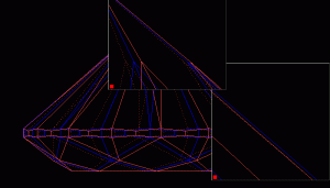
See illustration below. I had rotated red model from right direction on 5 degree.
You can see difference of ‘slopes main pavilion facet in projection’ for red and blue model


BruceISLopeAngleIdea.gif
 
excuse the crude art work.
is this what you are talking about?

amianidiot.jpg
 
Status
Not open for further replies. Please create a new topic or request for this thread to be opened.
GET 3 FREE HCA RESULTS JOIN THE FORUM. ASK FOR HELP
Top