shape
carat
color
clarity

AGS new cut grade system early 2005

Status
Not open for further replies. Please create a new topic or request for this thread to be opened.
Date: 10/29/2004 10:44:37 AM
Author: Diermint
Date: 10/29/2004 9:39:39 AM

Author: strmrdr


.2 degrees is the accuracy of the more common diamond scanners in use.

HCA, AGA, AGS or anything else based on the measurements is going to have that margin of error.

There are some better tools available or soon to be available but there will always be a margin of error it is just huge right now.

That''s interesting Strmrdr, thanks, I had just assumed they would be measured more accurately than that but I hadn''t ever looked into it before. Do you know offhand what the error in measuring the dimensions is - ie. they seem to be often quoted to the nearest 0.1mm - is that a limitation in the measurement or has it to do with the variability in the stone?
They are optical measuring devices which can be a good thing or bad.
Without getting to technical the resolution of the optical sensor, how well the optics work in getting the information to the sensors. and how well the software deals with the data determine the base accuracy.
The new scanners claim higher resolution sensors, better optics, and claim better software results.

One you get beyond talking about the base or machine accuracy you get into real world accuracy.
Optical measuring devices lost favor in industry after being the next big thing for a while because of the problem of keeping them clean.
They do not deal with dust, dirt or oil very well at all.
They are also hard to calibrate and that is where you get the biggest difference between the results from 2 scanners even if the base accuracy is the same.

Just an fyi a logitec 4000 CCD web cam has better resolution than the sensors used in even the newer scanners. But doesn''t have the level of noise filtering.

If I was going to design one I start with a 10 megapixel sensor. :}
ssssshhhh I know they have too bad a noise problem for that use yet. Which is why the lower resulution CCD sensors are used.
 
Date: 10/29/2004 10:29
6.gif
2 AM
Author: Serg
Marty,

re:Sergey: the four mains design (with 45 degree pavilion angles) is NOT a retroreflector ( EXCEPT for a parallel wavefront perpendicular to the table, e.g. GIA's DCLR illumination).


I know it. But I do not see any reason : Why you are not publishing result for stone with 'the four mains design (with 45 degree pavilion angles) is NOT a retroreflector '


We lost a lot of time for discussing what is retroreflector. Much more easy to publish result .

Sergey, here is the data for the models.. I spent a half hour writing up an explanation but the $#%&^* Internet Exploder kicked me off and I lost it. I'll do another write up

FOV metrics with 3 degree solid angle
WLR metrics cosine squared weighting, no GLARE
AGS Hemisphere has 33 degree solid andle head obsuration
GIA new hemisphere with 46 degree solid angle head

Note where FOV metrics are actually ZERO
NOTE THE RELATIVE IMPORTANCE OF GLARE, I think this is BS


EX_RR1.gif
 
Date: 10/31/2004 2:55:56 AM
Author: strmrdr

They are optical measuring devices which can be a good thing or bad.
Without getting to technical the resolution of the optical sensor, how well the optics work in getting the information to the sensors. and how well the software deals with the data determine the base accuracy.
The new scanners claim higher resolution sensors, better optics, and claim better software results.

One you get beyond talking about the base or machine accuracy you get into real world accuracy.
Optical measuring devices lost favor in industry after being the next big thing for a while because of the problem of keeping them clean.
They do not deal with dust, dirt or oil very well at all.
They are also hard to calibrate and that is where you get the biggest difference between the results from 2 scanners even if the base accuracy is the same.

Just an fyi a logitec 4000 CCD web cam has better resolution than the sensors used in even the newer scanners. But doesn''t have the level of noise filtering.

If I was going to design one I start with a 10 megapixel sensor. :}
ssssshhhh I know they have too bad a noise problem for that use yet. Which is why the lower resulution CCD sensors are used.

Some time ago I saw some quite impressive microtomography of an uncut diamond that was done on a synchrotron which showed pictures (and a movie) of exactly where the inclusions were located. I know this is a bit different, but do you think you could book a beamline for high-throughput measurements of cut diamonds? Would this give a greater accuracy? Has anyone looked into this before?
 
Date: 10/31/2004 10:53:50 PM
Author: Diermint
Date: 10/31/2004 2:55:56 AM
know this is a bit different, but do you think you could book a beamline for high-throughput measurements of cut diamonds? Would this give a greater accuracy? Has anyone looked into this before?
Can you clarify your question for me im not sure what your refering too with "book a beamline".
Serg or Gary may be able to answer this better than I am able too.
 
Date: 10/31/2004 9:39:17 PM
Author: adamasgem


Date: 10/29/2004 10:29
6.gif
2 AM
Author: Serg
Marty,

re:Sergey: the four mains design (with 45 degree pavilion angles) is NOT a retroreflector ( EXCEPT for a parallel wavefront perpendicular to the table, e.g. GIA's DCLR illumination).


I know it. But I do not see any reason : Why you are not publishing result for stone with 'the four mains design (with 45 degree pavilion angles) is NOT a retroreflector '


We lost a lot of time for discussing what is retroreflector. Much more easy to publish result .

Sergey, here is the data for the models.. I spent a half hour writing up an explanation but the $#%&^* Internet Exploder kicked me off and I lost it. I'll do another write up

FOV metrics with 3 degree solid angle
WLR metrics cosine squared weighting, no GLARE
AGS Hemisphere has 33 degree solid andle head obsuration
GIA new hemisphere with 46 degree solid angle head

Note where FOV metrics are actually ZERO
NOTE THE RELATIVE IMPORTANCE OF GLARE, I think this is BS
Sorry Folks.. I screwed up and used my Model 11 (M11 Eppler/Kluppelberg(1) 1940) as a reference point on the previous table which should have been the Tolkowsky model. Corrected data to follow.
 
Marty, I have two questions about your modeling of NEW GIA Brightness model

1) Why you write 1,5 degree FOV? GIA use 3 degree of pupil
2) Are you modeling 1,5 (3) degree con FOV in infinity or 1,5(3) degree of pupil FOV for distance 400mm ?
 
Date: 11/1/2004 2
6.gif
5:51 AM
Author: Serg

Marty, I have two questions about your modeling of NEW GIA Brightness model

1) Why you write 1,5 degree FOV? GIA use 3 degree of pupil
2) Are you modeling 1,5 (3) degree con FOV in infinity or 1,5(3) degree of pupil FOV for distance 400mm ?
Sergey Here is my data correctly normalized to Tolkowsky values

GIA shows a 3 degree solid angle which is +/- 1.5 deg from the table normal, I think, at least that is the way I interpreted it.
So I collect rays that emerge within 1.5 degrees of the table normal,
I effectively do it at infinity in the way I look at it..

If you believe otherwise, how do you think I should do it, GIA wasn''t very clear in what they ment, I went by their picture of the hemisphere..

EX_RR2.gif
 
Hi Strmrdr,

I''ve had a bit of a look on the net and found that there''s some info regarding using synchrotron for uncut diamonds, see:

http://www-fp.mcs.anl.gov/xray-cmt/rivers/diamonds.html

These images can be made into 3D images like usual CAT scans only much better resolution. Unfortunately I can''t find a 3D diamond reconstruction.

We''re getting a new synchrotron down here in Australia - it''s being built at the moment in Melbourne near Monash University and will hopefully be commissioned in the next couple of years (2006/7).
The advantage with the synchrotron is that it allows greater resolution due to the brighter light source and it can provide almost any light source including right through to hard x-ray (some which can be useful for diamonds). The synchrotron can also provide many different light sources all at once and are harnessed through ''beamlines''. Many synchrotrons throughout the world will rent out beamlines by the hour or by the day - it can be expensive but if you can analyse lots of samples then it can be worth it. Some industries set up samples to be scanned automatically during their allocated time and could do hundreds per hour.

Anyway, I was wondering if anyone knew if anyone had looked into using this for measuring cut diamonds and whether it was worth doing on a large scale. Assuming it is a lot more accurate then is it advantageous enough to warrant the price?


Diermont
 

"..This virtual observer only detected light from the diamond from a face-up position and within a narrow- 3 angular spread- area( Like a person who looks at a diamond from a mostly fixed position and from a reasonably close distance, in this case about 14-20 inches - roughly 35-50 cm - as we noted in most trade observations).."" G&G Fall 2004 P 215.


Unfortunately we have at least two interpretations.


For distance 400 mm , 3 degree will give 21mm FOV


For Diamond 6 mm it is 3, 86 degree FOV in infinity. Area is more on 65%.


I use 21 mm FOV for GIA new metric. May be it is wrong interpretation.


P/S I have small suggestion. +-1.5 degree FOV is 3 Degree FOV. 1.5 degree FOV is misleading.


Pyramidal/Tolkowsky WLR Metric =1.246


Is a good proof why WLR Metric is very bad.


Marty,
Do you have any plans to publish results for RD45?
 
Date: 11/1/2004 3
6.gif
4:27 AM
Author: Diermint
Hi Strmrdr,

I've had a bit of a look on the net and found that there's some info regarding using synchrotron for uncut diamonds, see:

http://www-fp.mcs.anl.gov/xray-cmt/rivers/diamonds.html

These images can be made into 3D images like usual CAT scans only much better resolution. Unfortunately I can't find a 3D diamond reconstruction.

We're getting a new synchrotron down here in Australia - it's being built at the moment in Melbourne near Monash University and will hopefully be commissioned in the next couple of years (2006/7).
The advantage with the synchrotron is that it allows greater resolution due to the brighter light source and it can provide almost any light source including right through to hard x-ray (some which can be useful for diamonds). The synchrotron can also provide many different light sources all at once and are harnessed through 'beamlines'. Many synchrotrons throughout the world will rent out beamlines by the hour or by the day - it can be expensive but if you can analyse lots of samples then it can be worth it. Some industries set up samples to be scanned automatically during their allocated time and could do hundreds per hour.

Anyway, I was wondering if anyone knew if anyone had looked into using this for measuring cut diamonds and whether it was worth doing on a large scale. Assuming it is a lot more accurate then is it advantageous enough to warrant the price?


Diermont

Diermont,


I am very sorry, but your proposal is nonsense.


There are o lot of optical methods to receive much better accuracy ( than by synchrotron ) for 3d model of surface polish diamond.


or do you want to change color of diamond ?

 
Ok... Just wondering... Is it the time factor or a lack of accuracy?
 
Date: 11/1/2004 3:52:29 AM
Author: Diermint
Ok... Just wondering... Is it the time factor or a lack of accuracy?

Firstly : Time and cost.


The accuracy of optical method is enough for diamond industry.


Remark: microtomography of diamonds has some benefits( If we speak about dust, oil ,.. on diamond surface) . But There are possible to find its by optical method too.

The main question is price.
 
Thanks Sergey, that''s what I was wanting to know.

I remember being quite taken with the movie I saw showing the 3D image but you''re right, to do a full scan would take quite a bit of time layer by layer.

Anyway, just throwing ideas around...
 

Better resolutions is not imply better accuracy.( especially for microtomography)

 
Date: 11/1/2004 4:11:36 AM
Author: Diermint
Thanks Sergey, that's what I was wanting to know.

I remember being quite taken with the movie I saw showing the 3D image but you're right, to do a full scan would take quite a bit of time layer by layer.

Anyway, just throwing ideas around...
http://www.skyscan.be/next/spec_1172.htm

Reconstruction time :6.8 sec per cross section 1Kx1K pixels (float point cone-beam reconstruction, 0.9 deg./step)


Workstation with Dual Intel XEON 3.2 GHz , 2GB RAM (optional - up to 4GB
 
Yes, and the scanning time looks like quite a while too, even on the "1078_ultrafast", 3:15 minutes at only 47um pixel size.

But just imagine what that time would have been like 5 or 10 years ago and imagine what it''ll be like in another 5 or 10.
2.gif
 
Sergey has done some development work for a company producing this type of device some years back.

There is a bone scanning device in an Adelaide Australia medical unit that uses this type of approach. He does know what he is talking about D :)

With diamonds - 1. there is a need to know what proportions to cut
2. The cutting must be done with precision (this may be done with higher precision than the current ability of most devices to measure it).
3. Measuring acurtaely is only important if you have a method of grading cut that requires such accuracy.
Since HCA and AGS proportions are just a few parameters - other factors like symmetry, alignment and minor facets mean that the inherent error in these approaches is more significant than table, crown and pavilion angle data.

However we believe that AGS and GIA will be performing some 3D model calculations. In this case Helium will provide a new level of accuracy.
 
Marty AGS FOV should be 30 degrees solid angle. The blue light represents above 75 degrees, and the red is above 45 degrees (with green below 45).
 
style="WIDTH: 99%; HEIGHT: 146px">Date: 11/1/2004 3:33:43 AM
Author: Serg


Pyramidal/Tolkowsky WLR Metric =1.246


Is a good proof why WLR Metric is very bad.


Marty,
Do you have any plans to publish results for RD45?
Sergey , please enlighten me regarding your interpretation of the relative results of the pyramidal model.
I know it has a "steep pavilion", but the model is "designed" so to speak, to minimize light loss from parallel ray inputs, and nothing more, to my way of thinking. But I may be missing something
2.gif


Re: RD45, I hadn''t planned to as I have no published data to compare with. I guess I could add the "new" definitions to my "list" of defined stones. I need to redo the way I am handling that anyway and allow specific designs to be saved before they are run.
 
Date: 11/1/2004 5:58:28 AM
Author: Garry H (Cut Nut)
Marty AGS FOV should be 30 degrees solid angle. The blue light represents above 75 degrees, and the red is above 45 degrees (with green below 45).
Thanks Gary: It wasn''t clear when I was given the "zone" definitions above what the FOV they were using was for their metric. I was told the "head" obscuration was a 33 degree solid angle.
 
Date: 11/1/2004 10:25:41 AM
Author: adamasgem

style="WIDTH: 97.26%; HEIGHT: 13px">

Sergey , please enlighten me regarding your interpretation of the relative results of the pyramidal model.
I know it has a ''steep pavilion'', but the model is ''designed'' so to speak, to minimize light loss from parallel ray inputs, and nothing more, to my way of thinking. But I may be missing something
2.gif


Re: RD45, I hadn''t planned to as I have no published data to compare with. I guess I could add the ''new'' definitions to my ''list'' of defined stones. I need to redo the way I am handling that anyway and allow specific designs to be saved before they are run.

90-45-45 degree pyramidal diamond model is designed to see pupil. In other words it is very dark diamond with very high GIA WLR.

You could publish Your calculation of GIA and your metrics for RD45 and other new diamonds. It is interesting because we have not GIA results for new GIA metrics and new GIA diamonds.
You could do it later when it will convenient for you.
 
Date: 11/1/2004 3:25:21 AM
Author: Serg


''..This virtual observer only detected light from the diamond from a face-up position and within a narrow- 3 angular spread- area( Like a person who looks at a diamond from a mostly fixed position and from a reasonably close distance, in this case about 14-20 inches - roughly 35-50 cm - as we noted in most trade observations)..'''' G&G Fall 2004 P 215.


Unfortunately we have at least two interpretations.


For distance 400 mm , 3 degree will give 21mm FOV


For Diamond 6 mm it is 3, 86 degree FOV in infinity. Area is more on 65%.


I use 21 mm FOV for GIA new metric. May be it is wrong interpretation.


P/S I have small suggestion. +-1.5 degree FOV is 3 Degree FOV. 1.5 degree FOV is misleading.

Regarding nomenclature, I agree. I missed that sentance in the article, I used the picture to infer their definition.

A 6mm stone at 400mm only subtends a solid angle of 0.86 degrees. A definition of Pupil size would absolutely define the exit angles wrt the table that could be observed, but that depends on the physical size of the stone, and GIA''s analysis appears to be non dimensional, although they have defined the diameters of the stones used as exemplars.

From what they say, and their "dome" observations alluded to, it would appear that the "observers" were not "dark adapted" viewers. Perhaps that is why their models didn''t correlate well with their "observations", as they used a fixed "FOV" in the theoretical, while the angular light collection ability varied with "dome" and/or other environmental conditions as well as the size (diameters) of the stones.
 
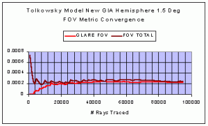
I ran convergence for the tolkowsky model on the restricted FOV metric as a function of number of rays traced

FOVcon1.gif
 
I''m beginning to wonder more and more about the GIA model "correlations" with observations, and the scientific usefullness of what they publish regarding this whole mess. I started making a file based on the incomplete model defs in the Fall 2004 G&G, and noticed that the data indicates:

1) The table sizes are basically quantized at 1% increments
2) The star facet lengths are basically quantized at 5% increments
3) The pavilion girdle lengths are basically quantized at 5% increments
4) Inadequate girdle and culet information

Now I ask, given the Fall 1999 G&G article Figure 12, page 179, which shows radically differing "views" of a diamond versus sensitivity to star facet length, is any of this supposed "measurement" data usefull, or accurate enough for judging relative performance of a diamond. Look at their virtual pictures!
 
Date: 11/1/2004 1:49:59 PM
Author: adamasgem
I''m beginning to wonder more and more about the GIA model ''correlations'' with observations, and the scientific usefullness of what they publish regarding this whole mess. I started making a file based on the incomplete model defs in the Fall 2004 G&G, and noticed that the data indicates:

1) The table sizes are basically quantized at 1% increments
2) The star facet lengths are basically quantized at 5% increments
3) The pavilion girdle lengths are basically quantized at 5% increments
4) Inadequate girdle and culet information

Now I ask, given the Fall 1999 G&G article Figure 12, page 179, which shows radically differing ''views'' of a diamond versus sensitivity to star facet length, is any of this supposed ''measurement'' data usefull, or accurate enough for judging relative performance of a diamond. Look at their virtual pictures!
And Marty, they have clearly different proportions for some stones - does this indicate that some have been recut (as they suggest) or are they covering up for scanning errors? + or - 5% is a huge difference.
BTW Marty when you model their stones - you know that the length and the depth or Lower Girdles are different? There are two measurement methods and GIA use a different method than everyone else - their 75% = approx 78% for everyone else.
we need Beryl''s chart for these calculations - not that they will be that useful with such a large rounding.

I do not have the fire article with me (on a weeks vacation) but when i looked - the photo''s of some diamonds appeared to be the exactly the same.
Can someone post the link to the fire article on line please?
 
http://www.gia.edu/pdfs/Fall_2001_Cut.pdf
 
Date: 11/1/2004 5:13:48 PM
Author: Garry H (Cut Nut)

Date: 11/1/2004 1:49:59 PM
Author: adamasgem
I''m beginning to wonder more and more about the GIA model ''correlations'' with observations, and the scientific usefullness of what they publish regarding this whole mess. I started making a file based on the incomplete model defs in the Fall 2004 G&G, and noticed that the data indicates:

1) The table sizes are basically quantized at 1% increments
2) The star facet lengths are basically quantized at 5% increments
3) The pavilion girdle lengths are basically quantized at 5% increments
4) Inadequate girdle and culet information

Now I ask, given the Fall 1999 G&G article Figure 12, page 179, which shows radically differing ''views'' of a diamond versus sensitivity to star facet length, is any of this supposed ''measurement'' data usefull, or accurate enough for judging relative performance of a diamond. Look at their virtual pictures!
And Marty, they have clearly different proportions for some stones - does this indicate that some have been recut (as they suggest) or are they covering up for scanning errors? + or - 5% is a huge difference.
BTW Marty when you model their stones - you know that the length and the depth or Lower Girdles are different? There are two measurement methods and GIA use a different method than everyone else - their 75% = approx 78% for everyone else.
we need Beryl''s chart for these calculations - not that they will be that useful with such a large rounding.

I do not have the fire article with me (on a weeks vacation) but when i looked - the photo''s of some diamonds appeared to be the exactly the same.
Can someone post the link to the fire article on line please?
In the 2004 G&G they said they used 3 different diameter hemisphere 6", 12" and 16"
The 3 degree "hole" in the hemisphere has chords of 4, 8 and 10.6mm, but in correlating viewer data on the 45 stones

I would hope they didn''t use the 10.6mm as a pupil diameter, rather large I would say.

Pupil diameter models range from 2 mm(photopic) to 8mm(scotopic), depending on the field luminance, in the literature I''ve read

Their stones range from 6.2mm (0.89ct) to 4.9mm(0.44ct) in diameter...

BUT since they didn''t say what the "viewer" was (scotopic or photomic) they didn''t define the pupil size, which is needed to calculate a "true" observation angle TOA, in their example..

where TOA=arctangent(0.5*(Diameter_pupil+Diameter_stone)/Radius_hemisphere)

They would have to use this physical model to correlate with their data..

I''m changing my software to just use the physical models for TOA, and change the TOD for the particular stones physical or assumed diameter, but what this means is that observation metrics have to be related to the size of the stone observed.

For a strongly photopic viewer D_pupil=2mm, in a 16" hemisphere

TOA for a 6.2mm stone is 1.15 degrees
TOA for a 4.9mm stone is 0.97 degrees

If the viewer is stongely scotopic(Dark adapted) D_pupil=8.0mm, in a 16" Hemisphere
TOA for a 6.2mm stone is 4.0 degrees
TOA for a 4.9mm stone is 3.6 degrees

I was erroneously using a fixed 1.5 degree TOA in the data I presented, but unfortunately we don''t know what GIA calculated or in fact used. We don''t know the luminance in their hemisphere so we don''t know what the basis is for their general model.
 
You raise some interesting issues concerning the idea of a peer review article Marty.
I will make a request that we are given some answers to such questions.

I believe one of the important tenents of ''peer reviw'' is that any study can be reproduced by any other student skilled in the field. If, as it seems, there is insufficient information in the curent or previous GIA Cut Study G&G articles, it is reasonable to request the information that is lacking.
 
Someone correct me if i am wrong, but in my previous post on total angle of acceptance TOA, it seems that the larger the stone, the wider the range of angles of rays with respect to the table the viewer will "process" as being part of the stone.

If we fix the TOA (TOA_fixed), as is suggested in the GIA article, and then try to correlate with observations with a varying "real" TOA (TOA_ith), then if

TOA_fixed
we can''t possibly get any "good" correlation of the theoretical TOA_fixed model with the observed.


Status
Not open for further replies. Please create a new topic or request for this thread to be opened.
GET 3 FREE HCA RESULTS JOIN THE FORUM. ASK FOR HELP
Top