shape
carat
color
clarity

GIA''s amazing new patent

Status
Not open for further replies. Please create a new topic or request for this thread to be opened.

Shay37

Ideal_Rock
Joined
Mar 1, 2004
Messages
3,343
Date: 1/26/2007 5:59:37 PM
Author: adamasgem


Date: 1/26/2007 5:27:56 PM
Author: Rhino


Date: 1/26/2007 5:16:33 PM
Author: strmrdr
You know something about my answer bugged me and after thinking about it...

Can average angles of 8 facets ever be considered true or actual?
None of the facets may actualy have that specific number.
Answer: Yes. The proper wording IMO would be 'They are the actual average crown angles.'
emsmiled.gif
It is my understanding that the scanners use the stepped pedestal to calibrate the system.

It might be interesting to check the scanners linear calibration using square steel guage blocks, which can be obtained for $25 bucks or so in 1/4 inch sizes with linear tolerances +/- 0.000005 inches 0r equivilently +/- 0.000125mm

A small right angle optical prism to check angle accuracy or consistency might also prove informative, as one can flip it..

Of course the apriori model the scanner is trying to solve for would have to be changed. I don't know how difficult that would be. Have to check with Sarin on that, or maybe Serg could comment..

PS I would avoid the use of the word 'actual' and replace it with 'measured'
Clever, Marty. Thus the inference of actual only if the measuring device is indeed accurate. Considering the headache after following sort of thus far, difficult to ascertain if the measuring device is accurate, and therein lies the crux.

shay

edited for clarity
 

adamasgem

Brilliant_Rock
Joined
May 23, 2003
Messages
1,338
Date: 1/26/2007 10:23:31 PM
Author: Shay37
Clever, Marty. Thus the inference of actual only if the measuring device is indeed accurate. Considering the headache after following sort of thus far, difficult to ascertain if the measuring device is accurate, and therein lies the crux.

shay

edited for clarity
Well, as I stated before, one can use inexpensive traceable (traceable to NIST standards) "calibrated" references, such a guage blocks, to check the linear measurements. It is done with weights every day, and with micrometers also, although I dout there are one out of ten out there that do it. Most labs have some sort of procedure, I believe, maybe not on an absolute basis, but they might run tthe same stone day after day to sanity check the devices.
 

strmrdr

Super_Ideal_Rock
Joined
Nov 1, 2003
Messages
23,295
Date: 1/26/2007 10:23:31 PM
Author: Shay37
Clever, Marty. Thus the inference of actual only if the measuring device is indeed accurate. Considering the headache after following sort of thus far, difficult to ascertain if the measuring device is accurate, and therein lies the crux.

shay

edited for clarity
This is where DiamCalc and models comes into play.
Take the full file with all the readings import it into diamcalc and look at the calculated heart image.
How close is too the real image?
There will be some variation due to different h&a viewers and building a calibrated DC model of the scope would be a huge help here.

Right now helium wins by a wide margin.
The new sarin software may bring it closer but ogi is a joke at this point.

Why use the hearts?
It takes 5 facets measured right to get each heart true to life.
the same reason they are the best indication of optical symmetry.
 

kenny

Super_Ideal_Rock
Premium
Joined
Apr 30, 2005
Messages
33,601
Boy, I'll bet GIA must HATE Pricescope.
 

RockDoc

Ideal_Rock
Joined
Aug 15, 2000
Messages
2,509
Date: 1/26/2007 11:08:18 PM
Author: kenny
GIA must HATE Pricescope.

Hey Kenny

GIA doesn''t hate Pricescope. I think they receive good information from it.

I will grant you that when something they do isn''t correct, or other experts "challenge" their methodology they benefit from it.

No one likes "egg on their face", and Marty''s ciritique style when they "screw up", I''m sure they find embarrasing. But Marty being an engineer and scientist, is usually correct about what he writes, and does it with the intention of helping both consumers and the industry.

GIA does try to keep "everyone" happy...... Whether it should or not in certain decisions, is questionable. However when one hold themselves to be the "Authority", you also open yourself to being embarrassingly criticized when you "goof".

Marty does have a "distinct" style in the way he comments. Is he always "politically correct" in his style. No.... he isn''t, but everyone gets the point in the style by which he does write, and what he does write is usually in excruiating detail and supported well.

The industry is "lucky" to have a Marty out there, keeping an eye out for raising the bar.

But I''d also say that Marty probably won''t get a Valentine''s Card from the powers to be at GIA either. But somehow, even if he did, it would probably end up in a certain fancy lit litter box.

Rockdoc
 

Serg

Ideal_Rock
Trade
Joined
Mar 21, 2002
Messages
2,659
Date: 1/26/2007 5:03:22 PM
Author: Rhino

Date: 1/26/2007 3:42:54 PM
Author: strmrdr
Have a question why does the ogi always seem to get the pavilion angle .2 degrees shallower than sarin are they measuring them different?
Or is the ogi just that lame?
It''s algorythm for computing pavilion angles are different from Sarin/Helium to my knowledge. I don''t have the details in front of me. Garry or Marty may know more of the details off the cuff.
OGI Pav height 3.11/ OGI diameter 7.20=43.2%
In same time OGI Pav height%=42.8
 

diagem

Ideal_Rock
Trade
Joined
Oct 21, 2004
Messages
5,096
Question:

Why round shape GIA reports include "profile to actual proportions" vs. Fancy shapes that their profile is "not" actual proportions...?

makes you wonder, no?
 

Garry H (Cut Nut)

Super_Ideal_Rock
Trade
Joined
Aug 15, 2000
Messages
18,655
Date: 1/27/2007 2:20:40 AM
Author: Serg

OGI Pav height 3.11/ OGI diameter 7.20=43.2%
In same time OGI Pav height%=42.8
Politics in mathematics and data presentation.

It is what I have referred to often as the surveyors closed loop creative mathematics.

GIA suggest that they use rounding to compensate for the current accuracy of scanners, yet they have tested helium and know that the methods they use for round brilliant cut quality grading with facetware are based on scan data that they do not use for facet meet point grading or girdle thickness analysis.

Common sense is not common.
 

Garry H (Cut Nut)

Super_Ideal_Rock
Trade
Joined
Aug 15, 2000
Messages
18,655
Date: 1/26/2007 4:29:57 PM
Author: Adylon
One thing I''d REALLY like to see on a grading report is some tolerances.

54.8 +/- 0.2% table, 62.7 +/- 0.3% depth or something to that affect.

It would be very nice if they gave tolerances of their human-observed grading as well, like clarity, color, etc, but I don''t think that''s going to happen any time soon because of all the politics surrounding that topic of course. But when something is measured by machine or gauge, why not specify what the precision of that tool is?
Adylon since GIA caters mainly for a US market, one should start with the education system by teachiing first what plus and minus mean.

By that time it is likely that all the old scanners would be worn out and the problem would be long solved.
 

adamasgem

Brilliant_Rock
Joined
May 23, 2003
Messages
1,338
Date: 1/27/2007 2:20:40 AM
Author: Serg

OGI Pav height 3.11/ OGI diameter 7.20=43.2%
In same time OGI Pav height%=42.8
GOOD OBSERVATION Serg... New GIA Arithmetic???

At least the GIA graphic doesn''t put the mm''s on it so that the same type of ERROR won''t appear, but since GIA now uses OGI for their FarceWare(TM), I wonder if it inherent there in their (GIA) data also... GIA doesn''t put he absolute measurement on their report.

I guess it is a warning to OGI users, especially appraisers, who rely on these numbers for there reports, and legal liability issues..

I wonder how long Gem Instruments is going to last as part of GIA. Rumour has it that they have moved it off campus to enable storage of all the unsold KittyDocks(TM)
emotion-14.gif


adamasgem

Brilliant_Rock
Joined
May 23, 2003
Messages
1,338
Date: 1/27/2007 6:32:00 AM
Author: Garry H (Cut Nut)

Adylon since GIA caters mainly for a US market, one should start with the education system by teachiing first what plus and minus mean.

By that time it is likely that all the old scanners would be worn out and the problem would be long solved.
emotion-19.gif
You may be right there Garry
 

Rhino

Ideal_Rock
Trade
Joined
Mar 28, 2001
Messages
6,341
Shay hit the nail on the head IMO.

"Considering the headache after following sort of thus far, difficult to ascertain if the measuring device is accurate, and therein lies the crux."

Marty, I''ve developed a way to determine the accuracy of scanners which strm touched upon in the post above.

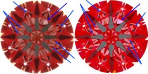
When a diamond is scanned it produces a 3 dimensional model based on those measurements. With the ability to import that model into DiamCalc one can then check the detailed optical results of the model through the various views DiamCalc produces. Strm alluded to the hearts view which is one way to do a good check. The one view in DiamCalc that has been most useful to me for checking the accuracy of a scanner is the former IdealScope view that existed in version 2.4. The reason I like the former IS view is because it showed internal reflections and even nuances among those internal reflections that we can capture in photography. Below is an example of a model generated on the stone vs a photograph of the actual stone. Note the contrast between the dark vs light reds in the stars, under the table, the tiny blacks where the lower halves and pav mains intersect etc.

The deviations between the optics the model produces vs the actual photograph of the stone give me an excellent indicator as to the accuracy of the scan. When the similarities are as strong as they are in this example, any differences and the photograph take precedence because its the actual stone.

There is an answer I think in helping get all Sarin''s on the same page.

Firstly use a properlly calibrated Sarin wherein the model can be checked in this fashion.
Secondly, create a calibration file that Sarin can load on the web ... notify all their users to download and calibrate their own machines with the 1 file so there is a universal standard. This way at least all the Sarin''s will be on target. With the availability of downloads via the Internet on a global scale I don''t see how that can''t be a possibility. Then all our scanners will produce the same results including GIA''s & AGS'' Sarin. Wouldn''t that be neat?

Peace,

scannercalib.jpg
 

Rhino

Ideal_Rock
Trade
Joined
Mar 28, 2001
Messages
6,341
Date: 1/27/2007 2:20:40 AM
Author: Serg

Date: 1/26/2007 5:03:22 PM
Author: Rhino


Date: 1/26/2007 3:42:54 PM
Author: strmrdr
Have a question why does the ogi always seem to get the pavilion angle .2 degrees shallower than sarin are they measuring them different?
Or is the ogi just that lame?
It''s algorythm for computing pavilion angles are different from Sarin/Helium to my knowledge. I don''t have the details in front of me. Garry or Marty may know more of the details off the cuff.
OGI Pav height 3.11/ OGI diameter 7.20=43.2%
In same time OGI Pav height%=42.8
Thanks Serg.

Correct me if I''m wrong but isn''t Helium measuring paviloin angles off the right angle from the girdle while OGI does it off the table? Can you elaborate a bit for clarification?

Thanks,
 

strmrdr

Super_Ideal_Rock
Joined
Nov 1, 2003
Messages
23,295
Date: 1/27/2007 6:32:00 AM
Author: Garry H (Cut Nut)

Date: 1/26/2007 4:29:57 PM
Author: Adylon
One thing I''d REALLY like to see on a grading report is some tolerances.

54.8 +/- 0.2% table, 62.7 +/- 0.3% depth or something to that affect.

It would be very nice if they gave tolerances of their human-observed grading as well, like clarity, color, etc, but I don''t think that''s going to happen any time soon because of all the politics surrounding that topic of course. But when something is measured by machine or gauge, why not specify what the precision of that tool is?
Adylon since GIA caters mainly for a US market, one should start with the education system by teachiing first what plus and minus mean.

By that time it is likely that all the old scanners would be worn out and the problem would be long solved.
tsk tsk that was not nice.
Thats like saying all aussies stay drunk all the time and snuggle crocs.
 

RockDoc

Ideal_Rock
Joined
Aug 15, 2000
Messages
2,509
Secondly, create a calibration file that Sarin can load on the web ... notify all their users to download and calibrate their own machines with the 1 file so there is a universal standard. This way at least all the Sarin''s will be on target. With the availability of downloads via the Internet on a global scale I don''t see how that can''t be a possibility. Then all our scanners will produce the same results including GIA''s & AGS'' Sarin. Wouldn''t that be neat?


______________________

Neat idea, Jon - but I don''t think it''s one that would work.

1. Each Sarin model is different. So the calib setting for each would vary slightly. Then how about the older units, versus the newer units?

2. Light settings will vary due to the age of the bulb in the unit for setting the calibration voltage settings.

3. Getting the histograms precisely the same to the nnnth degree would be nice also, but I don''t believe that is attainable.

4. Lens variances.. IF we each scanned a stone using a different lens, that has to have some affect to in the results. So to be exact we would have to state in reports which lens was used to scan the stone with.

5. Stone size differences. We all agree that there is a higher level of scan accuracy based on larger stone sizes being less prone to variance than smaller ones.

Gage blocks as Marty suggested and is a topic for one of the AGS conclave seminars is also scheduled in April, may help attain a universal "standard", but as Im sure you know even the the same machine making two scans of the same stone, using the same calib settings, you can get slightly varying results on the dimensions/measurements, and since the percentages are calculated based on that - I don''t think we can achieve the accuracy standard to that small a variance that you suggest is possible using a global calbration set of settings.

But....... the tech guys are rather amazing with what they invent, so maybe they will make this possible in the future.

Guess we need to put that on our wish list to Sarin.

In the meantime, we have to just accept the very slight variances I suppose.

Rockdoc
 

San Francisco

Rough_Rock
Joined
Nov 10, 2005
Messages
16
Geeee….I thought GIA already owned the patent on the round brilliant cut diamond.

Why would they need another patent on measuring it?

By the way, does De Beers own GIA or is it the other way around?


It is a slow rainy Saturday in San Francisco…..
 

diagem

Ideal_Rock
Trade
Joined
Oct 21, 2004
Messages
5,096
Date: 1/27/2007 12:16:59 PM
Author: San Francisco

Geeee….I thought GIA already owned the patent on the round brilliant cut diamond. no such thing...

Why would they need another patent on measuring it?


By the way, does De Beers own GIA or is it the other way around? Guys, can you imagine if they did!?!?


It is a slow rainy Saturday in San Francisco…..
 

adamasgem

Brilliant_Rock
Joined
May 23, 2003
Messages
1,338
Date: 1/27/2007 11:10:15 AM
Author: Rhino

Thanks Serg.

Correct me if I''m wrong but isn''t Helium measuring paviloin angles off the right angle from the girdle while OGI does it off the table? Can you elaborate a bit for clarification?

Thanks,
Good point..The Crown angle had always been referenced to the girdle plane, to my memory, but I see NOW that GIA has changed that to reference it to the table, which makes absolute sense in a way, since the table plane is somewhat uniquely defined, providing the scanner pedestal is flat with no perturbances.
I have seen distortions when we tried to put a 0.5 carat stone on the wrong pedestal and the table dipped into the pedestal vacuum hole.

see http://www.diamondcut.gia.edu/05_diamond_anatomy.html

Their pictures in all the previous literature show the crown angle relative to an "imaginary" girdle plane.

One of the problems is, to define the girdle plane parameters from the overdefined girdle edge min-maxs around the stone. I

Sarin seems to "define" all girdle facets orthoganal to the table, based on the normals in STLs I have seen, where Helium seems to do it "correctly" as their normals on girdle facets (virtual facets by necessity, if the stone is bruted) vary, as should be expected by faceting and rounding constraints.

I have been playing with algorithms to resolve these data from the mesh data provided, and the best solution I have come up with is to average (weighted because of the variable uncertainties in defining the normals, or straight average) the normals of the girdle facets, and then take the orthogonal to that to determine the girdle plane..
 

adamasgem

Brilliant_Rock
Joined
May 23, 2003
Messages
1,338
Date: 1/27/2007 11:05:50 AM
Author: Rhino

Firstly use a properlly calibrated Sarin wherein the model can be checked in this fashion.

Secondly, create a calibration file that Sarin can load on the web ... notify all their users to download and calibrate their own machines with the 1 file so there is a universal standard. This way at least all the Sarin''s will be on target. With the availability of downloads via the Internet on a global scale I don''t see how that can''t be a possibility. Then all our scanners will produce the same results including GIA''s & AGS'' Sarin. Wouldn''t that be neat?

Peace,
Rhino.. I don''t see how the highlighted phrase can do what you want it to do. Each system would need their own file based on the same stone, and then each user would have to scan that particular stone to find the errors vis a vie the factory calibration data. I believe Sarin suppies data on the matched optics/pedestal pairs which are used to self calibrate the system, in a linear sense. They may correct for any pin-cushion or barrell distortion in the optics, but I am not sure.

Sarin''s calibration, I believe, is based on the individual optics and alignment relative to each system''s multiple pedestal measurements. The step in the pedestal provides the necessary information for the linear calibration.

The best solution, I believe, is to use NIST traceable guage blocks for the linear measurements, as I commented on before, or to reserve a stone yourself and check for consistency in measurement of that stone, but that (a stone) would require probably some software changes by Sarin (or other manufacturers) to accomplish what is needed.
 

Serg

Ideal_Rock
Trade
Joined
Mar 21, 2002
Messages
2,659
Date: 1/27/2007 11:10:15 AM
Author: Rhino

Date: 1/27/2007 2:20:40 AM
Author: Serg


Date: 1/26/2007 5:03:22 PM
Author: Rhino


Date: 1/26/2007 3:42:54 PM
Author: strmrdr
Have a question why does the ogi always seem to get the pavilion angle .2 degrees shallower than sarin are they measuring them different?
Or is the ogi just that lame?
It''s algorythm for computing pavilion angles are different from Sarin/Helium to my knowledge. I don''t have the details in front of me. Garry or Marty may know more of the details off the cuff.
OGI Pav height 3.11/ OGI diameter 7.20=43.2%
In same time OGI Pav height%=42.8
Thanks Serg.

Correct me if I''m wrong but isn''t Helium measuring paviloin angles off the right angle from the girdle while OGI does it off the table? Can you elaborate a bit for clarification?

Thanks,

Rhino,
OGI, Sarin, Helium are measuring angles with reference to table( holder plane) . All scanners use same reference. In Helium you can use horizon for reference also.
I do not know definition of holder plane based on Z-coordinates crown and pavilion lines girdle, which is correct for any type girdle. Also we can not use surface girdle for finding girdle axis due low accuracy ( thickness of girdle is few pixels)
 

Serg

Ideal_Rock
Trade
Joined
Mar 21, 2002
Messages
2,659

End even if you can find girdle plane correctly it does not mean what girdle plane is best reference always.


Take 3 equal cut with ideal symmetry( in all type definitions)
1) In first diamond tilt table
2) In second diamond tilt(rotate) girdle( all facets)
3) In third diamond move culet

and now mix it all for fourth diamond .


For first diamond girdle plan is right reference plane
For second diamond table plane is right reference plan

What is right reference plane for fourth diamond?
 

adamasgem

Brilliant_Rock
Joined
May 23, 2003
Messages
1,338
Date: 1/27/2007 1:30:21 PM
Author: Serg


Rhino,
OGI, Sarin, Helium are measuring angles with reference to table( holder plane) . All scanners use same reference. In Helium you can use horizon for reference also.

I do not know definition of holder plane based on Z-coordinates crown and pavilion lines girdle, which is correct for any type girdle. Also we can not use surface girdle for finding girdle axis due low accuracy ( thickness of girdle is few pixels)
Serg.. Wouldn''t the sheer number of cirdle facet centroids be sufficient to adequately define the girdle plane coefficients and compensate for the relative uncertainty of the girdle facet definitions????

How do you create a measure of table/girdle plane misalignment (not parallel) anyway, as that was alway taught as a measure of stone quality, or do you compute that?
 

adamasgem

Brilliant_Rock
Joined
May 23, 2003
Messages
1,338
Date: 1/27/2007 1:45:03 PM
Author: Serg

End even if you can find girdle plane correctly it does not mean what girdle plane is best reference always.


Serg, I agree that the table is the best defined datum...

I guess then you could take a parallel to the table through the average girdle facets Z axis component to define the reference girdle plane and look at the computed girdle plane based on the girdle plane facet centroids to define the girdle plane tilt..

The same type of issue arise regarding use of the girdle plane measuremnts when you calculate the min and max diameters.

How those stone diameters defined, as the girdle facet edges are not necessarily 180 degrees opposed from each other.

You can compute the largest included circle inside the computed girdle facet planes and the smallest external circle formed by the facets and use that information...We are down in the minutia, but it seems that some defined and consistent theoretical methodology is in order.

When we use a leveridge guage, the stone tends to rock and align against the nearest opposing girdle facet planes, and that is an error in itself technically, let alone trying to find the mins and max points. In a bruted girdlle stone, the contact instumentation tends to seek opposing "flats" also.
 

Serg

Ideal_Rock
Trade
Joined
Mar 21, 2002
Messages
2,659
Date: 1/27/2007 2:35:23 PM
Author: adamasgem

Date: 1/27/2007 1:30:21 PM
Author: Serg


Rhino,
OGI, Sarin, Helium are measuring angles with reference to table( holder plane) . All scanners use same reference. In Helium you can use horizon for reference also.


I do not know definition of holder plane based on Z-coordinates crown and pavilion lines girdle, which is correct for any type girdle. Also we can not use surface girdle for finding girdle axis due low accuracy ( thickness of girdle is few pixels)
Serg.. Wouldn''t the sheer number of cirdle facet centroids be sufficient to adequately define the girdle plane coefficients and compensate for the relative uncertainty of the girdle facet definitions????

How do you create a measure of table/girdle plane misalignment (not parallel) anyway, as that was alway taught as a measure of stone quality, or do you compute that?
re:Wouldn''t the sheer number of cirdle facet centroids be sufficient to adequately define the girdle plane coefficients and compensate for the relative uncertainty of the girdle facet definitions????


Marty,

6 pixels height can( not perfect algorithm) produce 10 degree( 2 sigma for example)

64 facets will reduce deviation in 8 times only


0.6 degree sigma is too much. Even 0.2 degree sigma ( from real nice algorithm) is too bad accuracy for reference plane


If we are speaking about table /girdle misalignment 0.5 degree accuracy is enough. But It is too low accuracy fro reference plane for pavilion angles
 

adamasgem

Brilliant_Rock
Joined
May 23, 2003
Messages
1,338
Date: 1/27/2007 3:05:03 PM
Author: Serg


re:Wouldn't the sheer number of cirdle facet centroids be sufficient to adequately define the girdle plane coefficients and compensate for the relative uncertainty of the girdle facet definitions????


Marty,

6 pixels height can( not perfect algorithm) produce 10 degree( 2 sigma for example)


64 facets will reduce deviation in 8 times only


0.6 degree sigma is too much. Even 0.2 degree sigma ( from real nice algorithm) is too bad accuracy for reference plane


If we are speaking about table /girdle misalignment 0.5 degree accuracy is enough. But It is too low accuracy fro reference plane for pavilion angles

Maybe I shouldn't have said centroids..
1) You have more data than that (64 points) by virtue of the number of resolver steps taken
2) The X axis position of the girdle facets can probably be better defined by using a shadowing type of algorithm based on the intensity of the CCD pixels along the vertical edge.

3) The Y components of the girdle vertices might be better resolved by using intersections of the profile line segments making up the crown or pavilion facets and possiblly along with the intensity of the pixel at the intersection, with the assumption of meet point faceting.

Easier said than done, but you get the point.

How do you handle the non orthogonality (tilt) and positioning of the pedestal with the optic axis of the scanner? Isn't that a similar problem with the Y coordinate, although you have a longer base length to work with. The plane of the holder (pedestal on which the table rests.
 

Rhino

Ideal_Rock
Trade
Joined
Mar 28, 2001
Messages
6,341
Date: 1/27/2007 12:58:50 PM
Author: adamasgem

Date: 1/27/2007 11:05:50 AM
Author: Rhino

Firstly use a properlly calibrated Sarin wherein the model can be checked in this fashion.

Secondly, create a calibration file that Sarin can load on the web ... notify all their users to download and calibrate their own machines with the 1 file so there is a universal standard. This way at least all the Sarin''s will be on target. With the availability of downloads via the Internet on a global scale I don''t see how that can''t be a possibility. Then all our scanners will produce the same results including GIA''s & AGS'' Sarin. Wouldn''t that be neat?

Peace,
Rhino.. I don''t see how the highlighted phrase can do what you want it to do. Each system would need their own file based on the same stone, and then each user would have to scan that particular stone to find the errors vis a vie the factory calibration data. I believe Sarin suppies data on the matched optics/pedestal pairs which are used to self calibrate the system, in a linear sense. They may correct for any pin-cushion or barrell distortion in the optics, but I am not sure.

Sarin''s calibration, I believe, is based on the individual optics and alignment relative to each system''s multiple pedestal measurements. The step in the pedestal provides the necessary information for the linear calibration.

The best solution, I believe, is to use NIST traceable guage blocks for the linear measurements, as I commented on before, or to reserve a stone yourself and check for consistency in measurement of that stone, but that (a stone) would require probably some software changes by Sarin (or other manufacturers) to accomplish what is needed.
Thanks for sharing Marty & Bill. Perhaps some wishful thinking on my part but you''d think there''d be a practical solution to this.
14.gif
You have a pic of these NIST traceable gauge blocks? That sounds like it''d be a practical solution.
 

Rhino

Ideal_Rock
Trade
Joined
Mar 28, 2001
Messages
6,341
Date: 1/27/2007 1:30:21 PM
Author: Serg

Date: 1/27/2007 11:10:15 AM
Author: Rhino


Date: 1/27/2007 2:20:40 AM
Author: Serg


Date: 1/26/2007 5:03:22 PM
Author: Rhino


Date: 1/26/2007 3:42:54 PM
Author: strmrdr
Have a question why does the ogi always seem to get the pavilion angle .2 degrees shallower than sarin are they measuring them different?
Or is the ogi just that lame?
It''s algorythm for computing pavilion angles are different from Sarin/Helium to my knowledge. I don''t have the details in front of me. Garry or Marty may know more of the details off the cuff.
OGI Pav height 3.11/ OGI diameter 7.20=43.2%
In same time OGI Pav height%=42.8
Thanks Serg.

Correct me if I''m wrong but isn''t Helium measuring paviloin angles off the right angle from the girdle while OGI does it off the table? Can you elaborate a bit for clarification?

Thanks,


Rhino,
OGI, Sarin, Helium are measuring angles with reference to table( holder plane) . All scanners use same reference. In Helium you can use horizon for reference also.

I do not know definition of holder plane based on Z-coordinates crown and pavilion lines girdle, which is correct for any type girdle. Also we can not use surface girdle for finding girdle axis due low accuracy ( thickness of girdle is few pixels)
Thanks for this Serg. This is interesting news. All 3 scanners then use the table plane as a reference (which makes sense). If the OGI is using the table plane like Helium and Sarin are, I wonder why there always seems to be a discrepancy on their pavilion angles.
40.gif
I''d like to think it was just my unit however I was recently sent a brand new unit that is supposed to have their newer high def cams and the measuring results are pretty similar to what I was getting in my prior model.
 

Serg

Ideal_Rock
Trade
Joined
Mar 21, 2002
Messages
2,659
re:1) You have more data than that (64 points) by virtue of the number of resolver steps taken

Marty,
If diamond has 64 facet , additional photos can not increase accuracy significantly.( Because noise of camera is not real problem)
Main problem is
1) Fussy boundary between girdle and crown( pavilion)
2) ovalization boundary between girdle and crown( If you will take wrong point, angle of girdle facet will change a lot. But what is right point on ovalization edge?
 

Rhino

Ideal_Rock
Trade
Joined
Mar 28, 2001
Messages
6,341
Date: 1/27/2007 1:45:03 PM
Author: Serg

End even if you can find girdle plane correctly it does not mean what girdle plane is best reference always.


Take 3 equal cut with ideal symmetry( in all type definitions)
1) In first diamond tilt table
2) In second diamond tilt(rotate) girdle( all facets)
3) In third diamond move culet

and now mix it all for fourth diamond .


For first diamond girdle plan is right reference plane
For second diamond table plane is right reference plan

What is right reference plane for fourth diamond?
Good question. My guess would be the average of each of those planes.
33.gif


Here''s a question for ya Serg. If the Helium is using the table plane as its reference and the table is tilted will this skew the results of the Helium scan causing it to give faulty measurements?
 

adamasgem

Brilliant_Rock
Joined
May 23, 2003
Messages
1,338
Date: 1/27/2007 4:29:51 PM
Author: Serg

re:1) You have more data than that (64 points) by virtue of the number of resolver steps taken

Marty,

If diamond has 64 facet , additional photos can not increase accuracy significantly.( Because noise of camera is not real problem)
Main problem is
1) Fussy boundary between girdle and crown( pavilion)
2) ovalization boundary between girdle and crown( If you will take wrong point, angle of girdle facet will change a lot. But what is right point on ovalization edge?

1) On faceted girdles you could use the numerical intersections of the girdle plane with the crown or pavilion planes
2) Ovalization is probably more of a problem on bruted girdles.. You could test with 1) above for the endpoints whether the ovalization is "real" or not, just a guess..
 
Status
Not open for further replies. Please create a new topic or request for this thread to be opened.
Be a part of the community Get 3 HCA Results
Top