shape
carat
color
clarity

GIA''s amazing new patent

Status
Not open for further replies. Please create a new topic or request for this thread to be opened.
Date: 1/27/2007 4:33:07 PM
Author: Rhino

Good question. My guess would be the average of each of those planes.
33.gif


Here''s a question for ya Serg. If the Helium is using the table plane as its reference and the table is tilted will this skew the results of the Helium scan causing it to give faulty measurements?
Rhino The table and the pedestal planes are supposed to be coincident, the only way what you are suggesting could happen is if there is dirt under the table, and the table doesn''t make contact.
Their is the subtle issue of a tilted pedestal in all scanners.
 
Date: 1/27/2007 4:33:07 PM
Author: Rhino

Here''s a question for ya Serg. If the Helium is using the table plane as its reference and the table is tilted will this skew the results of the Helium scan causing it to give faulty measurements?
Rhino I think the answer is that since the stage and there fore the table is the reference plane - then the stone will have every other plane of symmetry tilted, but the table would be shown to be at ground "zero".

Remeber the stone I found that showed H&A''s yet GIA gave it only Good symmetry. You must have read this before - if you have not then please do now.

http://www.gemology.ru/cut/english/symmetry/6.htm

And hence the development of the crown and pavilion angle symmetry and variation at the bottom of helium reports titled "OctoNus Theory" that Sergey and Yuri developed as a result of this stone that I found and we wrote about in the above article.
 
If someone wants to check the angular accuracy of their scanner, look at right angle prisms from edmund

http://www.edmundoptics.com/onlinecatalog/displayproduct.cfm?productID=2329&search=1

the 5mm prism 5MM HT RA FS PRISM @ $80 has an angular spec of +/- 40 arc seconds or 0.0011 degree angular accuracy


Unfortunately 0.4 inch by 0.4 inch guage block ar probably about 1 inch long (25.4mm) , and they are not specificed for length accuracy, but cutting one in half will still give you two surfaces with specs of less than 0.000005 inches or 0.000127mm and the length random, the length could be lapped after cutting

see http://www1.mscdirect.com/CGI/NNSRIT?PMPXNO=2221210&PMT4NO=17209966

They would have to be cut, I can cut them and debur the edge for anyone who wants to try the experiment but I dont have the equipmet to guarantee parallism on the length.. but one width and the height would be within 0.000004 inches..
They are 31.12 each. If you have a Sarin that can handle the 23.4 inch length then you wouldn''t have to cut them..

Johnathon, does your Sarin handle a rectangle 25.4mm long ?
 
Date: 1/28/2007 3:23:37 AM
Author: adamasgem
If someone wants to check the angular accuracy of their scanner, look at right angle prisms from edmund

http://www.edmundoptics.com/onlinecatalog/displayproduct.cfm?productID=2329&search=1

the 5mm prism 5MM HT RA FS PRISM @ $80 has an angular spec of +/- 40 arc seconds or 0.0011 degree angular accuracy


Unfortunately 0.4 inch by 0.4 inch guage block ar probably about 1 inch long (25.4mm) , and they are not specificed for length accuracy, but cutting one in half will still give you two surfaces with specs of less than 0.000005 inches or 0.000127mm and the length random, the length could be lapped after cutting

see http://www1.mscdirect.com/CGI/NNSRIT?PMPXNO=2221210&PMT4NO=17209966

They would have to be cut, I can cut them and debur the edge for anyone who wants to try the experiment but I dont have the equipmet to guarantee parallism on the length.. but one width and the height would be within 0.000004 inches..
They are 31.12 each. If you have a Sarin that can handle the 23.4 inch length then you wouldn''t have to cut them..

Johnathon, does your Sarin handle a rectangle 25.4mm long ?
Helium rough measures stones up to +32mm wide Marty, height is less, but I doubt those prisms are accurate enough?
 
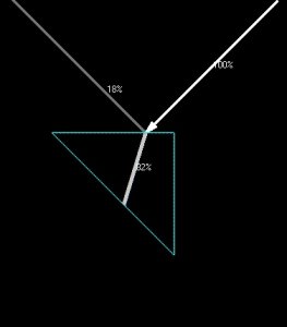
We have discussed making a section with a known angle and measuring the reflected angle over a long distance - say 100 meters - with a pin point laser light.

That way it would be possible to be sure the angle that was being measured was precise.

also I think the prism should not be regular as then the azimuth angle could be checked also.

45 degree reflection.jpg
 
Date: 1/28/2007 6:05:22 AM
Author: Garry H (Cut Nut)

Helium rough measures stones up to +32mm wide Marty, height is less, but I doubt those prisms are accurate enough?
Garry did you read the specs on the prism I GAVE you +/-40 arc seconds for the angle = 40/3600 = 1/90 degree = 0.011 degree (I erroneously said 0.0011 degree before)

the gage blocks better that 0.000005 inches x 25.4mm per inch = 0.000127mm

Both seem accurate enough to me for the purpose...
 
Rhino.

Since during the cutting process all the facets etc. are measured in relationship to the table I think it''s appropriate that any measuring device does the same.

If the table is skewed, it skews up (sic) all the rest of the measurements.

Rightly so, since a skewed table is cutting error.

Bill Bray
Diamond Cutter
 
Date: 1/28/2007 6:40:16 AM
Author: Garry H (Cut Nut)
We have discussed making a section with a known angle and measuring the reflected angle over a long distance - say 100 meters - with a pin point laser light.

That way it would be possible to be sure the angle that was being measured was precise.

also I think the prism should not be regular as then the azimuth angle could be checked also.
I agree with you there, but I haven''t been able to find commercially available (ie affordable) non right angle prisms that aren''t sloppier than the 40 arc sec spec yet.. (0.011 degree)

I guess the object is to have something under $100 or so that would afford a relatively good absolute standard..

A fairly simple solution would be a faceted CZs (laser engraved) with a large flat reference girdle facet, such that the midpoint of that facet could be easily found to establish an azimuth reference, and have it factory calibrated with a mesh file, and use that calibrated mesh file as a sanity check and/or aid to the calibration.

Scanner users should, at the very least, have a reference stone, and ad hoc do the same thing as a sanity check. The problem is in establishing the azimuth reference plane consistently, which is why I suggested a large reference flat girdle facet.

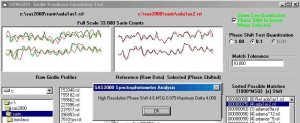
What I first did years ago, when the first Sarins came out, was prove that, from the old Sarin format RSL files, that one could phase up indipendently scanned girdle profiles in a data base and statistically find the same stone previously scanned... part of the SAS2000 software.. The same technique could be used to reestablish the azimuth zero point. I'''' generate an example and post it.
 
Here is an example of phasing up girdle profiles, for identification purposes (sorry GIA, you can''t patent it, it is public domain now), or establishing a zero azimuth position for run to run consistency checks... identifying like facets for run to run statistics, or calibration use..

It is a statistically powerfull tool for identification. These were done with 40 slice RSL girdle profiles..

Any comments Serg on the validity of the approach?

srngirx0.jpg
 
Date: 1/28/2007 6:05:22 AM
Author: Garry H (Cut Nut)

Helium rough measures stones up to +32mm wide Marty, height is less, but I doubt those prisms are accurate enough?

The gage block I suggested should work then.. Rhino could do it..
 
Date: 1/28/2007 3:09:17 PM
Author: adamasgem

Date: 1/28/2007 6:05:22 AM
Author: Garry H (Cut Nut)

Helium rough measures stones up to +32mm wide Marty, height is less, but I doubt those prisms are accurate enough?

The gage block I suggested should work then.. Rhino could do it..
He has the standard helium the max is around 8mm
 
Date: 1/28/2007 3:15:53 PM
Author: strmrdr

Date: 1/28/2007 3:09:17 PM
Author: adamasgem


Date: 1/28/2007 6:05:22 AM
Author: Garry H (Cut Nut)

Helium rough measures stones up to +32mm wide Marty, height is less, but I doubt those prisms are accurate enough?

The gage block I suggested should work then.. Rhino could do it..
He has the standard helium the max is around 8mm
The block would have to be cut down then in length.. Most are 1 inch long..
 
Why do you think there is a difference between girdle or table plane as a staring point for measurment purposes?
 
Date: 1/28/2007 3:32:44 PM
Author: DiaGem
Why do you think there is a difference between girdle or table plane as a staring point for measurment purposes?
The table plane is explictly defined by virtue of the pedestal, in the ideal case, while the girdle plane is ambiguous.. How do you define it (the girdle plane) is one of the problems as addressed above.
 
Date: 1/28/2007 3:53:36 PM
Author: adamasgem

Date: 1/28/2007 3:32:44 PM
Author: DiaGem
Why do you think there is a difference between girdle or table plane as a staring point for measurment purposes?
The table plane is explictly defined by virtue of the pedestal, in the ideal case, while the girdle plane is ambiguous.. How do you define it (the girdle plane) is one of the problems as addressed above.
Naturally it should be the table as it is calculated by cutters, no? the problem is that the table facet is sometimes tilted in the middle of the cutting process and the rest of the facets are not allways adjusted accordingly. With the girdle the same..., its position and angle depend greatly on which dop the cutter uses.

Other things that should be taking into consideration should be, the dop itself, i really dont know how many cutters use perfectly balanced dops.
And then comes the cutters table, vibrations from the engine/cutting disc do in my opinion offsets some of the precision!
 
Date: 1/28/2007 4:19:18 PM
Author: DiaGem

Date: 1/28/2007 3:53:36 PM
Author: adamasgem


Date: 1/28/2007 3:32:44 PM
Author: DiaGem
Why do you think there is a difference between girdle or table plane as a staring point for measurment purposes?
The table plane is explictly defined by virtue of the pedestal, in the ideal case, while the girdle plane is ambiguous.. How do you define it (the girdle plane) is one of the problems as addressed above.
Naturally it should be the table as it is calculated by cutters, no? the problem is that the table facet is sometimes tilted in the middle of the cutting process and the rest of the facets are not allways adjusted accordingly. With the girdle the same..., its position and angle depend greatly on which dop the cutter uses.

Other things that should be taking into consideration should be, the dop itself, i really dont know how many cutters use perfectly balanced dops.
And then comes the cutters table, vibrations from the engine/cutting disc do in my opinion offsets some of the precision!
The table tilted with respect to the girdle plane versus the girdle tilted with respect to the table plane are one and the same thing (maybe different signs). The topic is not an issue of how the stone is cut, but how it is measured and how to define mathematically the girdle plane.
 
RE: while the girdle plane is ambiguous.. How do you define it (the girdle plane) is one of the problems as addressed above.


Marty, I have that formula in my patent. There is a defined girdle center on the diamond, it''s an imaginary line just like the equator on the earth.

Cutters use it as a reference point and it has a direct relationship with the plane of the table, since that''s where it measures from.

Bill
 
Date: 1/28/2007 4:26:05 PM
Author: adamasgem

Date: 1/28/2007 4:19:18 PM
Author: DiaGem


Date: 1/28/2007 3:53:36 PM
Author: adamasgem


Date: 1/28/2007 3:32:44 PM
Author: DiaGem
Why do you think there is a difference between girdle or table plane as a staring point for measurment purposes?
The table plane is explictly defined by virtue of the pedestal, in the ideal case, while the girdle plane is ambiguous.. How do you define it (the girdle plane) is one of the problems as addressed above.
Naturally it should be the table as it is calculated by cutters, no? the problem is that the table facet is sometimes tilted in the middle of the cutting process and the rest of the facets are not allways adjusted accordingly. With the girdle the same..., its position and angle depend greatly on which dop the cutter uses.

Other things that should be taking into consideration should be, the dop itself, i really dont know how many cutters use perfectly balanced dops.
And then comes the cutters table, vibrations from the engine/cutting disc do in my opinion offsets some of the precision!
The table tilted with respect to the girdle plane versus the girdle tilted with respect to the table plane are one and the same thing (maybe different signs). The topic is not an issue of how the stone is cut, but how it is measured and how to define mathematically the girdle plane.
why specificaly the girdle plane? Whatever it be, shouldnt it be in coordination with a system to be used by cutters as well as measurers of the polished outcome?
 
Date: 1/28/2007 2:13:53 PM
Author: He Scores


Rhino.

Since during the cutting process all the facets etc. are measured in relationship to the table I think it''s appropriate that any measuring device does the same.

If the table is skewed, it skews up (sic) all the rest of the measurements.

Rightly so, since a skewed table is cutting error.

Bill Bray
Diamond Cutter
Correct from a craftsmanship point of view Bill

But as wrong as wrong can be from a light performance perspective.

A 1 degree table tilt = 2 degree variation in crown and pavilion
And a 1 degree table tilt is not perceptable visuall in an otherwise symmetrical stone.

Read the link I placed above and Sergey''s

For example a small out of round can have a 10 x greater impact.

A ray entering the table where there is 1 degree of titl is hardly bent by 1 degree of tilt, and if the pavilion axis is straight to the observer - then the stone looks perfctly symmetrical and would still show H&A''s as did the example in the linked article which GIA called Good Sym
 

Re: why specificaly the girdle plane? Whatever it be, shouldnt it be in coordination with a system to be used by cutters as well as measurers of the polished outcome?


Antique Diamond-Gem

Antique Diamond- Gem.....This is an astute observation!!

~~~~~~~~~~~~~~~~~~~~~~~~~~~~~~~~~~~~~`


Gary,

I read your article and I previously spoke with you about this on the phone one time. You are claiming that optically everything can be corrected by tilting the table. I respectfully disagree.

While you are correct that facets will be corrected 180 degrees from each other ASSUMING that the table is tipped EXACTLY from one of the will be corrected, you are incorrect however, that the error in the straightness of the facets 90 degrees to the tilt of the table will be corrected. They were made crooked to each other and to all of their neighbors by the cutter tipping the table. (Think in terms of spreading railroad tracks apart). No tilting of the stone will fix that. And if you think that this is a quick fix then I think that pretty much sums up performance grading and is yet another reason why performance grading and cut grading should be separate entities.

Also, what practical application does tilting the stone to correct the look achieve? Will you set the stone crooked in the head of the finished piece? I'm sure the customer will be delighted with that one.


Bill Bray
Diamond Cutter


Date: 1/28/2007 4:35:34 PM
Author: He Scores

RE: while the girdle plane is ambiguous.. How do you define it (the girdle plane) is one of the problems as addressed above.


Marty, I have that formula in my patent. There is a defined girdle center on the diamond, it''s an imaginary line just like the equator on the earth.

Cutters use it as a reference point and it has a direct relationship with the plane of the table, since that''s where it measures from.

Bill
Bill The "girdle center" (one point) does not define the girdle "plane". That point MAY lie in the girdle plane, but it is not what we are talking about here. Nor does a "line" define a "plane". I''ll look at your patent..
 
Date: 1/28/2007 6:33:07 PM
Author: He Scores


Re: why specificaly the girdle plane? Whatever it be, shouldnt it be in coordination with a system to be used by cutters as well as measurers of the polished outcome?


Antique Diamond-Gem

Antique Diamond- Gem.....This is an astute observation!!

~~~~~~~~~~~~~~~~~~~~~~~~~~~~~~~~~~~~~`


Gary,

I read your article and I previously spoke with you about this on the phone one time. You are claiming that optically everything can be corrected by tilting the table. I respectfully disagree.

While you are correct that facets will be corrected 180 degrees from each other ASSUMING that the table is tipped EXACTLY from one of the will be corrected, you are incorrect however, that the error in the straightness of the facets 90 degrees to the tilt of the table will be corrected. They were made crooked to each other and to all of their neighbors by the cutter tipping the table. (Think in terms of spreading railroad tracks apart). No tilting of the stone will fix that. And if you think that this is a quick fix then I think that pretty much sums up performance grading and is yet another reason why performance grading and cut grading should be separate entities.

Also, what practical application does tilting the stone to correct the look achieve? Will you set the stone crooked in the head of the finished piece? I''m sure the customer will be delighted with that one.


Bill Bray
Diamond Cutter


No Bill - I am saying that the table axes is one of many and it is the least important with the imaginary axis thru the pavilion as being the most important.

A reading from a scan indicates that all the other axes are way off if the table is tlited.

Labs wrongly use this data in a dumb way to make grading distinctions.

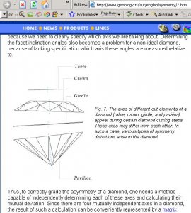
See the sketch - and if you do not understand what I have said then re-reading yuri''s artilce in full would be well advised.

symmetry article axes.JPG
 
Gary. We''re splitting hairs here and what hairs we''re splitting are more important to some people than to others.

Help me understand. I re-read that article. In it you say by adjusting the axis down through the table through the culet you can regain the symetry that was "ostensibly" lost when the table plane was inadvertantly tipped. If this is a correct interpretation then I will reiterate what I said before that NO SUCH CORRECTION takes place with the facets that are 90 degrees from the tilt.

You seem to aknowlegde this in item 2. Distorted Girdle Shape where you state and I quote :" However, such a shape of the girdle distorts the facet arrangement. First of all, it makes opposite facets non-parallel to each other, which dramatically changes the paths of light rays inside the diamond ".

This is exactly what I''m saying occurs when the table is tipped during the cutting process, but is not corrected by the adjustment of the table/culet axis.

And another thing. Cutter''s strive to make all these "axis" that you talk about parallel and perpendicular. If a stone that doesn''t have this occurring and still appears to be optically correct then the I think it is correct to assume that such a stone is inferior to one that does.


Time for my milk and cookies.

Bill
 
Of course a totally symetric diamond is best Bill.

But what we are doing is questioning the standards and practices of grading - and the severity of titled table shows up in every other axis being out of kilter under current systems.

This is wrong and it is bad and it is dumb.

I hope your system would not give a grade for a stone with a 1/2 dgegree titled table as not having a 1 degree variance in crown and pavilion angles and therefore bad symmetry
 
Date: 1/28/2007 3:07:33 PM
Author: adamasgem
Here is an example of phasing up girdle profiles, for identification purposes (sorry GIA, you can''t patent it, it is public domain now), or establishing a zero azimuth position for run to run consistency checks... identifying like facets for run to run statistics, or calibration use..

It is a statistically powerfull tool for identification. These were done with 40 slice RSL girdle profiles..

Any comments Serg on the validity of the approach?
Marty, We use combination rules for establishing a zero azimuth position.
ANY one rule is not enough usually for round diamond with perfect symmetry
 
Gary Said: I hope your system would not give a grade for a stone with a 1/2 dgegree titled table as not having a 1 degree variance in crown and pavilion angles and therefore bad symmetry.
~~~~~~~~~~~~~~~~~~~~~~~~~~~~

Let me make several points to which it seems that we're talking about now. For the statement above, no my system does not give "grades", so maybe that's the point of your argument, that such a slight error in cutting moves the "grade" to a lower status. My patented cut analysis would deduct points for each main angle over and under the targets of 34.5 on top and 40.75 on the bottom.

However, your statement implies that such a stone shouldn't recieve a grade, which I assume you meant "wouldn't give a low grade". So in answer to your wish above, if it was a top of the line stone (like you intimated that it has H&A patterning), then such a premium cut stone with a slight variation in table tip that would cause variations in main angle measures, there would actually have very little deductions for the variation in both the top and bottom main angles.

Actually, in the best case scenario, such a stone would have a score reduction in the 2.4% range. As a comparison, I've run scores on two identical top of the line 8* that the I-net seller thought were identically cut and the difference of score for them was in the 3% range. So you can see here that we're splitting hairs as I said before.

It should be noted that there is no cut grading system in use now other than BrayScore that can compare stones that closely or accurately.

Your example could very well recieve a high BrayScore IF THIS MAJOR CUTTING ERROR WERE THE ONLY THING WRONG THAT THE CUTTER DID. However, I would say that usually a premium manufacturer of goods would normally avoid this type of error, and in fact this error could have been produced perhaps even on the secondary market, but that's pure specualtion.

Also let me make another observation. I've always accepted the view that there were four types of stones.

1. Stones that look good to the eye and good on paper.
2. Stones that look good to the eye and bad on paper.
3. Stones that look bad to the eye and good on paper.
4. Stones that look bad to the eye and bad on paper.

Your complaint seems to be with the #2 stone that because of a grading system that depends on subjective human judgement or flawed analysis of data due to averaging and taking unimportant measurements, so I can appreciate where you're coming from, now that we've discussed it.

By using a cut analysis system like BrayScore, you may be happier because that stone could very well be moved to a #1 type of stone.

Bill Bray
Diamond cutter
 
Date: 1/29/2007 7:29:09 AM
Author: Serg

Date: 1/28/2007 3:07:33 PM
Author: adamasgem
Here is an example of phasing up girdle profiles, for identification purposes (sorry GIA, you can''t patent it, it is public domain now), or establishing a zero azimuth position for run to run consistency checks... identifying like facets for run to run statistics, or calibration use..

It is a statistically powerfull tool for identification. These were done with 40 slice RSL girdle profiles..

Any comments Serg on the validity of the approach?
Marty, We use combination rules for establishing a zero azimuth position.
ANY one rule is not enough usually for round diamond with perfect symmetry
Serg.. My example showed the applicability of picking one stone from similar stones done on the same scanner.. What I am suggesting is that the technique may be applicable for finding the SAME zero azimuth position on a single calibration stone.. the initial calibration done on a different scanner..

Obviously, additional "rules" can help

The issue is a robust algorith to enable comparison of the same facets on a run to run basis, that is why I suggested a calibration stone with a LARGE flat girdle facet as an additional reference point..
 
Bill and Garry.. The initial patent disscusion has degraded (becuse of the numbers issues and how they are defined) to WHAT defines, and HOW TO DEFINE the girdle plane, to grading of the table/girdle plane misalignment. Makes it difficult for the public to follow..

The "grading issues should be a different thread, I think.
 
Date: 1/29/2007 11:36:33 AM
Author: adamasgem


Date: 1/29/2007 7:29:09 AM
Author: Serg


Date: 1/28/2007 3:07:33 PM
Author: adamasgem
Here is an example of phasing up girdle profiles, for identification purposes (sorry GIA, you can't patent it, it is public domain now), or establishing a zero azimuth position for run to run consistency checks... identifying like facets for run to run statistics, or calibration use..

It is a statistically powerfull tool for identification. These were done with 40 slice RSL girdle profiles..

Any comments Serg on the validity of the approach?
Marty, We use combination rules for establishing a zero azimuth position.
ANY one rule is not enough usually for round diamond with perfect symmetry
Serg.. My example showed the applicability of picking one stone from similar stones done on the same scanner.. What I am suggesting is that the technique may be applicable for finding the SAME zero azimuth position on a single calibration stone.. the initial calibration done on a different scanner..

Obviously, additional 'rules' can help

The issue is a robust algorith to enable comparison of the same facets on a run to run basis, that is why I suggested a calibration stone with a LARGE flat girdle facet as an additional reference point..
Marty,
If you scan one diamonds on different Helium scanners you will receive same looks reports( same zero azimuth reference)

Accuracy for girdle facets can not be good enough for reference azimuth
 
Status
Not open for further replies. Please create a new topic or request for this thread to be opened.
GET 3 FREE HCA RESULTS JOIN THE FORUM. ASK FOR HELP
Top