shape
carat
color
clarity

GIA''s amazing new patent

Status
Not open for further replies. Please create a new topic or request for this thread to be opened.
Date: 1/31/2007 1:25:18 AM
Author: Garry H (Cut Nut)
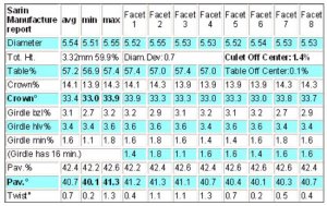
Here is its Sarin scanned .gem model.

There is a lower girdle facet error in the scan - the LG''s were longer than as represented - at the time there was a glitch - something i think to do with naming of lgf length and LGF depth.

The original scan date is sept 2002.
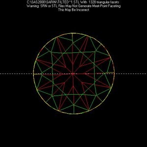
I ran the file through DC to get an STL file tht I can play with in my software, and I wasn''t very impressed with the crown regarding meet point faceteing. Perhaps if the scan is used to determine symmetry, that might wide up with a "good" Do you have the original SRN file. Is the girdle bruted on this stone?.

The normals to the girdle STLS were all over the place, and I couldn''t reconstruct, with my current girdle normals algorithm limits, a contiguous isolated girdle profile...(I arbitrarily call a facet a "girdle facet" if the normals to the plane are parallel to the table reference within 5 degrees.. Seems I have to rethink that issue, given the tilted table complexity.) I''ll up it to a 10 degree tolerance..
tilted.jpg
 
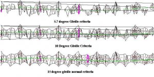
Here is whatI was able to resolve using a 5.7 degree and 10 degree girdle normal criteria.
Neglet the lines from one end to the other as they are artifacts from unfolding the girdle that I have to fix..

tiltedG.jpg
 
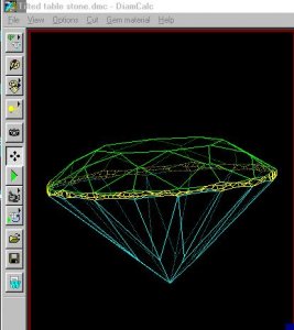
Lest Garry (or anyone else) question my ability to "identify" girdle facets, here is typically color coded Diamondcalc image from the same file Garry posted and that I processed.
Note on the crown and pavilion girdle intersections, small, presumingly girdle facets, that are color coded as belonging to the crown and or pavilion and INCORRECTLY NOT the girdle, I presume.

This is one of the issues with regard to using data from a scan, no matter how good the scan, in being able to identify the girdle plane, so that one can mathematically define it..

It also should be a wakeup to Bill Vray, regarding problems with "grading" based on problem scans, or problem stones.

Note also the lack of meet point faceting on the DC image crown, consistent with what I see in my software..

It is not only the scanner's ability to created a proper image, it is the analysis software's ability to automatically grab and properly process the information. Given that DiandCalc appears to have the same problem as I do in identifying what facets are part of the girdle, I wonder about the relative ability of FarceWare(TM) to do the same and render a proper verdict, as I think DiamondCalc and Helium are light years above OGI, from what I have seen, and I know I have a way to catch up to everything Serg does, but that was never my intention when I wrote the software for my SAS2000 users.

tiltDC.jpg
 
Date: 1/31/2007 4:56:27 PM
Author: adamasgem
Lest Garry (or anyone else) question my ability to ''identify'' girdle facets, here is typically color coded Diamondcalc image from the same file Garry posted and that I processed.
Note on the crown and pavilion girdle intersections, small, presumingly girdle facets, that are color coded as belonging to the crown and or pavilion and INCORRECTLY NOT the girdle, I presume.

This is one of the issues with regard to using data from a scan, no matter how good the scan, in being able to identify the girdle plane, so that one can mathematically define it..

It also should be a wakeup to Bill Vray, regarding problems with ''grading'' based on problem scans, or problem stones.

Note also the lack of meet point faceting on the DC image crown, consistent with what I see in my software..

It is not only the scanner''s ability to created a proper image, it is the analysis software''s ability to automatically grab and properly process the information. Given that DiandCalc appears to have the same problem as I do in identifying what facets are part of the girdle, I wonder about the relative ability of FarceWare(TM) to do the same and render a proper verdict, as I think DiamondCalc and Helium are light years above OGI, from what I have seen, and I know I have a way to catch up to everything Serg does, but that was never my intention when I wrote the software for my SAS2000 users.
I am not that familiar with this scan, but is the girdle bruted? If not, why cant it identify the actuall faceting arrangement of the girdle?
 
Date: 1/31/2007 4:56:27 PM
Author: adamasgem
Lest Garry (or anyone else) question my ability to ''identify'' girdle facets, here is typically color coded Diamondcalc image from the same file Garry posted and that I processed.
Note on the crown and pavilion girdle intersections, small, presumingly girdle facets, that are color coded as belonging to the crown and or pavilion and INCORRECTLY NOT the girdle, I presume.

This is one of the issues with regard to using data from a scan, no matter how good the scan, in being able to identify the girdle plane, so that one can mathematically define it..

It also should be a wakeup to Bill Vray, regarding problems with ''grading'' based on problem scans, or problem stones.

Note also the lack of meet point faceting on the DC image crown, consistent with what I see in my software..

It is not only the scanner''s ability to created a proper image, it is the analysis software''s ability to automatically grab and properly process the information. Given that DiandCalc appears to have the same problem as I do in identifying what facets are part of the girdle, I wonder about the relative ability of FarceWare(TM) to do the same and render a proper verdict, as I think DiamondCalc and Helium are light years above OGI, from what I have seen, and I know I have a way to catch up to everything Serg does, but that was never my intention when I wrote the software for my SAS2000 users.
Marty this was very early days when i was working as a go between with Avi from Sarin and Sergey to incorporate develop the capacity to import .srn files.

My scanner was only the DiaScan up to 12mm model - so this stone only filled 1/2 the screen.
2002 remember.

So your conclusions are accurate - but ancient history.
 
Date: 1/31/2007 5:53:10 PM
Author: DiaGem
I am not that familiar with this scan, but is the girdle bruted? If not, why cant it identify the actuall faceting arrangement of the girdle?
Garry would have to answer whether the stone was bruted, but the Sarin scans have greatly improved in accuracy, and I think, with the new software, are almost on a par with what I have seen shown for Helium.
 
Date: 1/31/2007 5:57:34 PM
Author: Garry H (Cut Nut)

Marty this was very early days when i was working as a go between with Avi from Sarin and Sergey to incorporate develop the capacity to import .srn files.

My scanner was only the DiaScan up to 12mm model - so this stone only filled 1/2 the screen.
2002 remember.

So your conclusions are accurate - but ancient history.
Then the Octonus article and your comments should have reflected that, IMHO.
I only used what you had posted to support your thesis, and the shortcoming should have been noted.
emotion-39.gif


Where is that old spanking gif, when you need it?
emotion-19.gif
 
the scanning issues were with the stl or .srn models Marty - Sarin had lousy azimuth data - and i doubt they can really improve that problem on their existing hardware platforms anyway.

The basic scan data used in that article was not at question however.

This is I believe the same stone from a seperate scan - there is a slight difference - but the same relative variantis there.

I no longer have the stone to do a helium scan :-(

titled table example stone.JPG
 
For what it's worth, perhaps for any retail consumers lurking, that stone of Gary's would have a BrayScore of 860. Well above average and probably close to what is normally called "ideal". It certainly isn't in the top 1% of the stones labled "top top ideal".

After looking at the data, it doesn't appear to be a classically tipped table. You'll notice on the bottom of the stone you have three higher angles, two average and three flat angles. This is classic table tipping measures.

However, you don't have that on top. The variations in the crown angles don't follow the same pattern and they should if their discrepancy were caused by table tipping.

Did Gary said this stone gave good H&A patterning.

Once again, looks can be deceiving.


Bill
 
Date: 1/31/2007 8:35:05 PM
Author: He Scores


For what it''s worth, perhaps for any retail consumers lurking, that stone of Gary''s would have a BrayScore of 860. Well above average and probably close to what is normally called ''ideal''. It certainly isn''t in the top 1% of the stones labled ''top top ideal''. You can only base that on a scan that would not be accurate enough - if i put a 1,000 stone on there - and scanned it - it would be what? 900 on 1 scan and 950 on the next?

After looking at the data, it doesn''t appear to be a classically tipped table. You''ll notice on the bottom of the stone you have three higher angles, two average and three flat angles. This is classic table tipping measures. Bill pair 1 with 5, 2 with 6, 3-7 4-8 and you will see you are wrong.

However, you don''t have that on top. The variations in the crown angles don''t follow the same pattern and they should if their discrepancy were caused by table tipping. Sarins top and bottom matching system glitch

Did Gary said this stone gave good H&A patterning. Bill - the photo''s of the stone are pasted above - and they are alos in the article that people do not seem to bother reading??????????

Once again, looks can be deceiving.


Bill
 
Date: 1/31/2007 8:35:05 PM
Author: He Scores


After looking at the data, it doesn''t appear to be a classically tipped table.

Bill

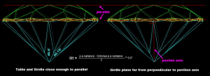
That''s because it''s not a classically tipped table. It''s girdle is equally tilted, so it would have avoided punishment from the GIA for a tilted table because they visually assess it relative to the girdle

Sure, it''s hard to define where the girdle plane actually is on this stone, but visually, it''s far closer to being parallel with the table than perpendicular with the pavilion axis (see diagram).

Hence I question Serg calling the table tilted. The diamond is vertically skewed.

And tieing in with the original topic of this thread, why does the GIA indicate on their holy proportion diagram that the crown and pavilion angles are relative to the girdle plane, if the table is God?


Fortunately the average pavilion and crown angles are not fooled by table tilt or vertical skewing, and it''s arguable whether the G symmetry grade was deserved or not for workmanship/cosmetic reasons, but I think the angles on Sarins and OGI reports should be normalised to give the real picture.


Stebbo

oct_tilt.png
 
Date: 2/1/2007 12:50:08 AM
Author: stebbo

Date: 1/31/2007 8:35:05 PM
Author: He Scores


After looking at the data, it doesn''t appear to be a classically tipped table.

Bill

That''s because it''s not a classically tipped table. It''s girdle is equally tilted, so it would have avoided punishment from the GIA for a tilted table because they visually assess it relative to the girdle

Sure, it''s hard to define where the girdle plane actually is on this stone, but visually, it''s far closer to being parallel with the table than perpendicular with the pavilion axis (see diagram).

Hence I question Serg calling the table tilted. The diamond is vertically skewed.

And tieing in with the original topic of this thread, why does the GIA indicate on their holy proportion diagram that the crown and pavilion angles are relative to the girdle plane, if the table is God?


Fortunately the average pavilion and crown angles are not fooled by table tilt or vertical skewing, and it''s arguable whether the G symmetry grade was deserved or not for workmanship/cosmetic reasons, but I think the angles on Sarins and OGI reports should be normalised to give the real picture.


Stebbo
That highlighted phrase is the confusion vector..
in GIA''s anatomy of a diamond http://www.diamondcut.gia.edu/05_diamond_anatomy.html
evrything is defined relative to the table..yet as you point out, they have this mythical girdle plane which no one has been able to define, since, even with your diagrams above, all the girdle "facets", theoretical in the case of a bruted girdle or actual in a faceted girdle, are not well defined or identified at all by the color coding..

I have been trying to take the centroids of all the girdle facets and use that overdefined set to define the "best" or optimal plane, which is the sought after mythical reference. There are a few ways of doing it, but if we knew the uncertainties of each girdle facet centroid, one could optimally produce this plane..Absence uncertainties, one is forced to use the overdefined set in a least squares sense..

The numbers bantied about to defien the table girdle plane tilt have no defined mathematical basis.

What we need is and explicit definition on how to define this plane...
 
Girdle palnes are often saddle shapped and not planes at all - they need not be flat.

They can be Einsteins time-space - you can see why here
http://com.pricescope.com/photos/stones/category1073/picture2235.aspx

What is wrong with our simple axis which is the average of all the points in a defined section?

Eg, table, crown cone using crown mains, girdle axis and pavilion axis using pavilion mains averages?

As to what GIA does - well - they ceased being leaders some time ago.
 
Date: 2/1/2007 4:32:31 AM
Author: Garry H (Cut Nut)
Girdle palnes are often saddle shapped and not planes at all - they need not be flat.

They can be Einsteins time-space - you can see why here
http://com.pricescope.com/photos/stones/category1073/picture2235.aspx

What is wrong with our simple axis which is the average of all the points in a defined section?

Eg, table, crown cone using crown mains, girdle axis and pavilion axis using pavilion mains averages?

As to what GIA does - well - they ceased being leaders some time ago.
The girdle is supposed to be defined by a plane in a perfect stone defined by the girdle facets, in my opinion.

Wavy girdles are cutting faults, period.

The number of girdle facets, virtual or otherwise, varies considerably.


Regarding the "average of all the points in a defined section" I''d like to see a definition of the "section", and what you mean by it.
As I pointed out above, even DiamondCalc could not "correctly", if you will, pick all the girdle "facets".
Tis a bitch to do, given all the variabilities.

I don''t think there is a simple definition of what and how to do it.

I agree regarding the GIA comment.

Been up all night, 7am and hitting the hay..
 
Crackies Gary. I sometimes think you're sole purpose in life is to say I'm wrong at any cost.

I saidAfter looking at the data, it doesn't appear to be a classically tipped table. You'll notice on the bottom of the stone you have three higher angles, two average and three flat angles. This is classic table tipping measures.

You said: Bill pair 1 with 5, 2 with 6, 3-7 4-8 and you will see you are wrong.

So let's see angles 1-5 are 41.2 and 40.4
2-6 41.3 40.1
3-7 41.1 40.3
4-8 40.7 40.7

For a dilettante who who never sat at the bench and cut, Gary, let me explain further. The angles 1-2-3 have a higher angle because the table was tipped from the top opposite side. Those corresponding angles on the crown should be lower than their opposites but they aren't.
This is why it isn't a classic tipping case. The top is just a case of shoddy cutting.
If 1-2 3 are made higher by the tipping the three opposite angles on the bottom are flat by equa measure which they are.

4-8 are angles that are 90 degrees to the tipping and their angles are unaffected. Their straightness is affected, but not their angle.

Your stone is a classic, optical symetry without physical symetry. As John pointed out in his discussion last night, it's obviously best to have both.

Selling optical symetry only as a top cut is selling optical ILLUSION.

Bill
 
Date: 2/1/2007 3:10:28 AM
Author: adamasgem

That highlighted phrase is the confusion vector..
in GIA's anatomy of a diamond http://www.diamondcut.gia.edu/05_diamond_anatomy.html
evrything is defined relative to the table..yet as you point out, they have this mythical girdle plane which no one has been able to define, since, even with your diagrams above, all the girdle 'facets', theoretical in the case of a bruted girdle or actual in a faceted girdle, are not well defined or identified at all by the color coding..

I have been trying to take the centroids of all the girdle facets and use that overdefined set to define the 'best' or optimal plane, which is the sought after mythical reference. There are a few ways of doing it, but if we knew the uncertainties of each girdle facet centroid, one could optimally produce this plane..Absence uncertainties, one is forced to use the overdefined set in a least squares sense..

The numbers bantied about to defien the table girdle plane tilt have no defined mathematical basis.

What we need is and explicit definition on how to define this plane...
Yes, the girdle plane is mythical and evading, so why try so hard to define something that is unimportant anyway? Ok, we want the table parallel to it for appear nice when set, but that's easily checked with a loupe. After all, a girdle exists just for something to grab on to, to prevent chipping and to retain weight. It's angle has little effect on light performance--it's just not important. It'd be great if it was easy to define an exact pavilon axis as this is where the action happens, but I suspect that might be just as impossible. Might as well just use the rock solid table plane.

Stebbo
 
Date: 2/1/2007 3:10:28 AM
Author: adamasgem


That highlighted phrase is the confusion vector..
in GIA's anatomy of a diamond http://www.diamondcut.gia.edu/05_diamond_anatomy.html
evrything is defined relative to the table..yet as you point out, they have this mythical girdle plane which no one has been able to define, since, even with your diagrams above, all the girdle 'facets', theoretical in the case of a bruted girdle or actual in a faceted girdle, are not well defined or identified at all by the color coding..

I have been trying to take the centroids of all the girdle facets and use that overdefined set to define the 'best' or optimal plane, which is the sought after mythical reference. There are a few ways of doing it, but if we knew the uncertainties of each girdle facet centroid, one could optimally produce this plane..Absence uncertainties, one is forced to use the overdefined set in a least squares sense..

The numbers bantied about to defien the table girdle plane tilt have no defined mathematical basis.

What we need is and explicit definition on how to define this plane...
The illustration was showing that there was no feasible girdle plane definition that would make the girdle not tilted as well (ie. perpendicular to the pavilion (where min and max pavilion mains approximate amount and direction of table tilt in this case)). It definitely didn't try to define the tilt of something that can't even be pictured.

Stebbo
 
Date: 1/27/2007 8:37:05 PM
Author: Garry H (Cut Nut)


Date: 1/27/2007 4:33:07 PM
Author: Rhino

Here's a question for ya Serg. If the Helium is using the table plane as its reference and the table is tilted will this skew the results of the Helium scan causing it to give faulty measurements?
Rhino I think the answer is that since the stage and there fore the table is the reference plane - then the stone will have every other plane of symmetry tilted, but the table would be shown to be at ground 'zero'.

Remeber the stone I found that showed H&A's yet GIA gave it only Good symmetry. You must have read this before - if you have not then please do now.

http://www.gemology.ru/cut/english/symmetry/6.htm

And hence the development of the crown and pavilion angle symmetry and variation at the bottom of helium reports titled 'OctoNus Theory' that Sergey and Yuri developed as a result of this stone that I found and we wrote about in the above article.
Apologies for my intermittent replies. A little hard for me to get here lately. I read the article Garry. It makes sense. A question for clarification ... does the Octonus Theory then take into account the view/measurements of the diamond along a proper pavilion axis if indeed the table is tilted?

For example in the first illustration of that H&A stone you had, there was a variance of 1.8 degrees shown in the pavilion angle which was due to the table tilt. Would the Octonus Theory show the real deal with regards to the precision of those pavilion angles ... like looking along a corrected table plane?

Thanks,
Jon

PS: I recall taking the shots of the last example in that article. Glad to be of some help.
 
Date: 2/1/2007 12:18:45 PM
Author: Rhino

Date: 1/27/2007 8:37:05 PM
Author: Garry H (Cut Nut)


Date: 1/27/2007 4:33:07 PM
Author: Rhino

Here''s a question for ya Serg. If the Helium is using the table plane as its reference and the table is tilted will this skew the results of the Helium scan causing it to give faulty measurements?
Rhino I think the answer is that since the stage and there fore the table is the reference plane - then the stone will have every other plane of symmetry tilted, but the table would be shown to be at ground ''zero''.

Remeber the stone I found that showed H&A''s yet GIA gave it only Good symmetry. You must have read this before - if you have not then please do now.

http://www.gemology.ru/cut/english/symmetry/6.htm

And hence the development of the crown and pavilion angle symmetry and variation at the bottom of helium reports titled ''OctoNus Theory'' that Sergey and Yuri developed as a result of this stone that I found and we wrote about in the above article.
Apologies for my intermittent replies. A little hard for me to get here lately. I read the article Garry. It makes sense. A question for clarification ... does the Octonus Theory then take into account the view/measurements of the diamond along a proper pavilion axis if indeed the table is tilted?

For example in the first illustration of that H&A stone you had, there was a variance of 1.8 degrees shown in the pavilion angle which was due to the table tilt. Would the Octonus Theory show the real deal with regards to the precision of those pavilion angles ... like looking along a corrected table plane?

Thanks,
Jon

PS: I recall taking the shots of the last example in that article. Glad to be of some help.
??? How did you help????

and yes - if you do some additionand subtraction - you will find it does calculate the average axis independant of the table tilt
 
Date: 2/1/2007 12:50:08 AM
Author: stebbo

Date: 1/31/2007 8:35:05 PM
Author: He Scores


After looking at the data, it doesn''t appear to be a classically tipped table.

Bill

That''s because it''s not a classically tipped table. It''s girdle is equally tilted, so it would have avoided punishment from the GIA for a tilted table because they visually assess it relative to the girdle

Sure, it''s hard to define where the girdle plane actually is on this stone, but visually, it''s far closer to being parallel with the table than perpendicular with the pavilion axis (see diagram).

Hence I question Serg calling the table tilted. The diamond is vertically skewed.

And tieing in with the original topic of this thread, why does the GIA indicate on their holy proportion diagram that the crown and pavilion angles are relative to the girdle plane, if the table is God?


Fortunately the average pavilion and crown angles are not fooled by table tilt or vertical skewing, and it''s arguable whether the G symmetry grade was deserved or not for workmanship/cosmetic reasons, but I think the angles on Sarins and OGI reports should be normalised to give the real picture.


Stebbo
Hi Stebbo,
Could you add to your fine 2D illustration green crown axis and yellow girdle axis

BTW What is pavilion axis in 3D? :) How can you define pavilion axis in 3D?
 
Date: 2/1/2007 2:02:22 PM
Author: Garry H (Cut Nut)

Date: 2/1/2007 12:18:45 PM
Author: Rhino


PS: I recall taking the shots of the last example in that article. Glad to be of some help.
??? How did you help????
Oh, yes thx Rhino - the girdle cheated stone
 
Date: 2/1/2007 4:53:39 PM
Author: Garry H (Cut Nut)

Date: 2/1/2007 2:02:22 PM
Author: Garry H (Cut Nut)


Date: 2/1/2007 12:18:45 PM
Author: Rhino


PS: I recall taking the shots of the last example in that article. Glad to be of some help.
??? How did you help????
Oh, yes thx Rhino - the girdle cheated stone
Correct. My memory''s not that bad ... yet.
5.gif
hehe Have a great evening.
 
Date: 2/1/2007 5:49:27 PM
Author: Rhino

Date: 2/1/2007 4:53:39 PM
Author: Garry H (Cut Nut)


Date: 2/1/2007 2:02:22 PM
Author: Garry H (Cut Nut)


Date: 2/1/2007 12:18:45 PM
Author: Rhino


PS: I recall taking the shots of the last example in that article. Glad to be of some help.
??? How did you help????
Oh, yes thx Rhino - the girdle cheated stone
Correct. My memory''s not that bad ... yet.
5.gif
hehe Have a great evening.
Garry does sometimes have selective memory loss regarding credits
17.gif

Like who gave him the info on the GIA patent that started this thread..
41.gif
 
Date: 2/1/2007 11:02:46 AM
Author: stebbo

Date: 2/1/2007 3:10:28 AM
Author: adamasgem


That highlighted phrase is the confusion vector..
in GIA''s anatomy of a diamond http://www.diamondcut.gia.edu/05_diamond_anatomy.html
evrything is defined relative to the table..yet as you point out, they have this mythical girdle plane which no one has been able to define, since, even with your diagrams above, all the girdle ''facets'', theoretical in the case of a bruted girdle or actual in a faceted girdle, are not well defined or identified at all by the color coding..

I have been trying to take the centroids of all the girdle facets and use that overdefined set to define the ''best'' or optimal plane, which is the sought after mythical reference. There are a few ways of doing it, but if we knew the uncertainties of each girdle facet centroid, one could optimally produce this plane..Absence uncertainties, one is forced to use the overdefined set in a least squares sense..

The numbers bantied about to defien the table girdle plane tilt have no defined mathematical basis.

What we need is and explicit definition on how to define this plane...
The illustration was showing that there was no feasible girdle plane definition that would make the girdle not tilted as well (ie. perpendicular to the pavilion (where min and max pavilion mains approximate amount and direction of table tilt in this case)). It definitely didn''t try to define the tilt of something that can''t even be pictured.

Stebbo
One could conceivably define two girdle planes, one, based on the crown facets junctions (measured from the table) and the othe based on the pavilion facet junctions measured from the table. Ideally bth planes should be parallel.
The normals to these planes serve to define the girlde tilts..
Doing that automatically, is another thing.
 
Date: 2/1/2007 3:27:27 PM
Author: Serg
Hi Stebbo,
Could you add to your fine 2D illustration green crown axis and yellow girdle axis

BTW What is pavilion axis in 3D? :) How can you define pavilion axis in 3D?

The crown axis -- lot harder than the pavilion as the opposite crown mains differences don't hint as strongly as to which direction the table might be tilted in, for this stone. I can't even approximate it.

A girdle axis -- Not convinced yet that it serves any advantage over the easily defined table axis, even if it could be easily defined.

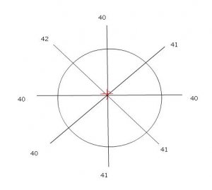
I'll have to think deeply as to whether it is possible to accurately define a 3d pavilion and crown axis. Even my 2d pavilion axis above was very approximate, and could not serve any exacting purpose due to making these assumptions:

  • that pav. mains 1 and 5 defined the direction of table tilt because they differed the most and tilt causes the greatest variance in the facets in it's direction. This might not be the case for a less well behaved pavilion.
  • that the direction of table tilt was exactly between pav. mains 1 and 5. I don't know enough about cutting/polishing to predict how likely this might be, but the amount of tilt is dependent on this.

Stebbo
 
Date: 2/1/2007 8:56:33 PM
Author: stebbo

Date: 2/1/2007 3:27:27 PM
Author: Serg
Hi Stebbo,
Could you add to your fine 2D illustration green crown axis and yellow girdle axis

BTW What is pavilion axis in 3D? :) How can you define pavilion axis in 3D?

The crown axis -- lot harder than the pavilion as the opposite crown mains differences don''t hint as strongly as to which direction the table might be tilted in, for this stone. I can''t even approximate it.

A girdle axis -- Not convinced yet that it serves any advantage over the easily defined table axis, even if it could be easily defined.

I''ll have to think deeply as to whether it is possible to accurately define a 3d pavilion and crown axis. Even my 2d pavilion axis above was very approximate, and could not serve any exacting purpose due to making these assumptions:


  • that pav. mains 1 and 5 defined the direction of table tilt because they differed the most and tilt causes the greatest variance in the facets in it''s direction. This might not be the case for a less well behaved pavilion.
  • that the direction of table tilt was exactly between pav. mains 1 and 5. I don''t know enough about cutting/polishing to predict how likely this might be, but the amount of tilt is dependent on this.

Stebbo
The average of the average of 4 sets of opposite pavilion mains

pav axis2.JPG
 
Stebbo.

When a cutter tips the table intentionally, he''ll "generally" try to come from a main table ribline. One reason for this is of course is that the facet that he tips from does not have to be corrected for straightness, using up girdle and thereby saving material. Of course, if it were done intentionally, it would be done well in the beginning of the cutting process and all angles and facet straightness would then be cut from the new table and the finished stone wouldn''t have a tipped table.

If it is tipped unintentionally it''s only by chance that it would run directly from a main facet, but it would still be a good chance since the tipping is caused by the "grain" "grabbing" on the wheel and since most main facets are laid out in accordance with the grain, it could come straight from the facet.

Now, what is meant by "exactly" is another story.

That''s my story and I''m sticking to it.

Bill
 
Date: 2/1/2007 6:08:50 PM
Author: adamasgem


One could conceivably define two girdle planes, one, based on the crown facets junctions (measured from the table) and the othe based on the pavilion facet junctions measured from the table. Ideally bth planes should be parallel.

Can you elaborate? It sounds better than the girdle facet normal criteria method.

Stebbo
 
Date: 2/1/2007 10:28:21 PM
Author: stebbo


Date: 2/1/2007 6:08:50 PM
Author: adamasgem


One could conceivably define two girdle planes, one, based on the crown facets junctions (measured from the table) and the othe based on the pavilion facet junctions measured from the table. Ideally bth planes should be parallel.

Can you elaborate? It sounds better than the girdle facet normal criteria method.

Stebbo
Let me clarify by illustrating the logic of the problem...

The normals to the girdle facets serve to DEFINE which facets are GIRDLE facets, i.e. you are given a general set of planes and the normals to the planes are examined to determine what facets are what. The normals to girdle facets typically lie within a few degrees parallel to the tabe plane in a wel cut stone, ideallly they (the normals of the girdle facets) are parallel to the table plane.

That is how you color code a facet diagram created from a Sarin mesh or a set of STL triangles..
When you have a general set of STL triangles, you are given the three vertices (which define a plane) and the normal to that plane. common normals lie on the same facet, and those STL's with common normals can be grouped an the individyal facet defined by a set of vectors defining the outline of the facet.

Eliminating the girdle facets, those facets with normals having a negative Z component belong to the crown and those with a positive Z component belong to the pavilion.

So each general facet is defined by a set of n vertices {v1,v2,v3,...vn}, Each vertex has a x,y, and z component

The GIRDLE facet sets define a mean Z component for the girlde facets. The rest of the facets can be adjusted relative to this mean value Z such that the crown facets have positive z componets to their vertices, and the paviolion facets have negative z components..

There is then a subset of the crown facets that are adjacent to the girdle plane, i.e. intersect girdle facet planes. With in this subset there are vertices or line (vector) segemnts {differences of two vertices} that DEFINE the crown/girdle boundary.

For example, ideally in a round brilliant, the crown mains would intersect the girdle at one vertex each, while the crown breaks intersect the girdle with line segments {made up of two or more vertices}. These are what can be used to define a plane such that no point {vertex} lies below that plane and the MAXIMUM amount of vertices lie on the plane.

This is what I would call the crown gridle plane. In the normally cut round brilliant, there are sixteen vertices from the crown that lie on that plane. Get the picture...

It is a constrained problem. Three crown vertices explicitly define a plane and no crown vertex can lie below that plane.
A little bit of arithmatic (as an understatement) but mathematically precise, and consistent with any round brilliant regardless of cutting stye {ie painted breaks}.
emotion-15.gif


Similarly, a pavilion girdle plane can be defined..

If the two planes so defined, intersect, they are not parallel. If either intersect the table, then the girdle is not parallel to the table.

In an ideally made normal round brilliant, sixteen vertices will lie on the crown girlde plane and sixteen will lie on the pavilion girlde plane.

PS They could be termed the crown scallop girdle plane and the pavilion scallop girdle plane
 
Date: 1/31/2007 4:42:44 PM
Author: adamasgem
Here is whatI was able to resolve using a 5.7 degree and 10 degree girdle normal criteria.
Neglet the lines from one end to the other as they are artifacts from unfolding the girdle that I have to fix..
I added the capability to vary the criteria used to define (select) the girdle facets, and here is a comparison of three limits used..
Seems the file Garry posted had some interesting variation in the planes defining the girdle profile and you needed at least a 15 degree criteria to adequately define what are girdle facets...

tiltGX.jpg
 
Status
Not open for further replies. Please create a new topic or request for this thread to be opened.
GET 3 FREE HCA RESULTS JOIN THE FORUM. ASK FOR HELP
Top